This thread has been locked.

If you have a related question, please click the "Ask a related question" button in the top right corner. The newly created question will be automatically linked to this question.

Using McASP with ADS8556 for receiving data in C6713

Other Parts Discussed in Thread: ADS8556

Hi,

I am using a C6713 with high-precision ADS8556 ADC's.

Here is my situation.

I have 6 channels of data coming from ADS8556 coming into the McASP1 serializer 5 (say)

in TDM Mode and another 6 channels of data coming from another ADS8556 into serializer 6

also in TDM mode.

What is the maximum clock that I can use for this kind of operation?

In the design, CONVST_A/B/C are connected to GPIO5/ EXT_INT5 of the DSP6713.

How can I generate the CONVST_A pulse as can be seen if I were to use DSP/BIOS?

Do you have any code for the setup and operation using McASP?

Thanks,

Aditi.


  • Hi Aditi,

    I don't have any code setup for the McASP of the TMS320C6713 to the ADS8556.  I might have something from the McBSP port, so I'll look around.  I will investigate the serializer clock as well to see what sort of speed you can get.

  • Tom,

    Have a quick question for you.

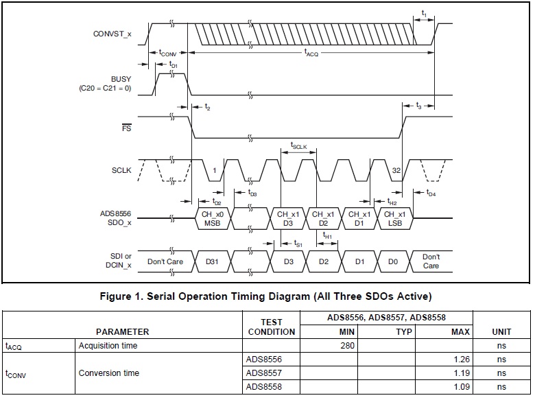
    Looking at the timing diagram (attached below) of ADS8556 for serial interface (data),

    the Max conversion time is 1.26 ns.

    What if the CONVST_x signal is high for say 10 us? Will the acquisition start soon after 1.26 ns?

    Or will the acquisition start after the FS goes low?

    Aditi.


  • Hi Aditi,

    You've actually stumbled across a little typo in the data sheet.  The units in that table are wrong, it should by 'micro' seconds, not 'nano' (see the Electrical Characteristics tables on pages 4-6 for clarification - this table will be updated in the next DS revision).  That being said, if the CONVST is held high for the 10us, the device will still enter the acquisition phase (sample and hold switch closes) after the conversion is complete - 1.26us in this particular case.  The rising edge of CONVST opens the sample and hold and begins the next conversion sequence.

  • Tom,

    So you mean to say that after the acquisition, we can read the data anytime after the acquisition is done

    but after FS goes low? Is that correct?

    Thanks

    Aditi

  • Hi Aditi,

    With the rising edge of CONVST, the conversion will start - this is the point where BUSY goes high in Figure 1.  Once the conversion is complete (after BUSY goes low) is when you want to read the data.  The acquisition phase starts up automatically after the conversion is complete, so technically you are acquiring the next sample while reading out the current conversion cycle data. 

    We normally use BUSY as an interrupt source, you can use that to trigger a data read sequence by driving FS low and starting the data transfer from the ADS8556 to the TMS320C6713.  The process would be the same for either the serial or parallel interface option.  In parallel mode, you would use the FS input like a chip select.

  • Tom.

    I already have the board and it has been designed as follows.

    1) ADS8556 connected to C6713 DSP using the McASP port so AFSR and ACLKR from the McASP connected

    to the FS and CLK of the ADC.

    2) GPIO5/EXT_INT5 pin of C6713 connected to the ADS8556.

    3) BUSY pin of ADS8556 connected to a test point.

    4) SEL_A is connected to +3.3V and SEL_B and SEL_C =0, so all the 6 channel data is transmitted from the ADC

    on SDO_A.

    I have initialized the McASP, for the 6 channel operation.

    Is there something that you think can be done to GPIO so that the CONVST and AFSR are synchronized.


    Also, do you think CH_C, CH_B, CH_A bits (31-29) of the Control register of ADS8556 be enabled in HW mode to start conversion of data??

    Thanks,
    Aditi.

  • Hi Aditi,

    I'm not sure that you can do that  - there is no way I know of to synchronize a GPIO to a McASP event. 

    One thing you might be able to do is to tie the test point for BUSY to the AFSR - set FSRM in the AFSRCTL register to '0' for an externally generated signal and FSRP to 1 for a falling edge on receive.  Set your GPIO/EXT_INT 5 to an 'input' and try using FSX from the McBSP port as the strobe for CONVST.  If you send a dummy transfer to the transmitter of the McBSP toggling CONVST high, that should set BUSY high and set up your McASP for data reception.  Using TOUT1 may work as CONVST as well if you set it for PULSE mode.

  • Forgot to mention, bits 31-29 do not apply in HW mode (see table 3, page 29).

  • Tom,

    In C6713, TOUT0/TOUT1 are pin-multiplexed with AXR[2]/AXR[4] signals.

    I am not sure if this is a possibility because we use the AXR[2] and AXR[4].

    Aditi.