This thread has been locked.

If you have a related question, please click the "Ask a related question" button in the top right corner. The newly created question will be automatically linked to this question.

ADS1158: For Fixed-Mode, Single-Ended conversions, and , what should MUXSCH's AINNX be set to?

Part Number: ADS1158
Other Parts Discussed in Thread: OPA2365

Hi,

We've been using Scan-Mode and the lowest Data-Rate, but the values are not as close as we would expect.   We would like to experiment with Fixed-Channel-Mode.

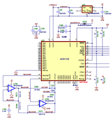
Based on the datasheet, the config register is set for Fixed-Mode , external ADCInP/N, and Chop-Enable,  (i.e. Reg 0x00 changed from 0x1E to 0x3E )

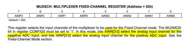
However, since all 16 channels are single-ended, and the external conditioner is present, what value does MUXSCH's AINNX expect since all AIN inputs are in reference to AInCom/MuxOutN/AdcInN.

Also, are there any other changes to the register-configuration and/or the circuit, that could improve accuracy?   For example, given an input voltage of 1.35v at the ADC, the ADS1158 reports 0x2871-0x2874, which would equate to about 1.38 (0x2873 * 4.096v/30720).

  • Hi Erich Zamora,

    As per the ADS1158 datasheet, the first four bits of the MUXSCH register select the positive analog channel (AINP) and the last four bits of the MUXSCH register select the negative analog channel (AINN) in Fixed-Channel Mode. Therefore, you need to select a channel for AINN from the available inputs (AIN0 through AIN15). As a result, only 15 single-ended inputs are realizable using the ADS1158 in Fixed-Channel Mode.

    Regarding accuracy: the best solution here would be to identify where your noise / error is coming from and remove that source of error (or calibrate it out). I don't know how you could change the register settings to improve this, other than by slowing down the ADC to improve noise performance (assuming that is the major source of error)

    I would also point out that the OPA2365 is not a true rail to rail amplifier. Since the OPA negative supply is grounded, the output needs to stay a few 10s of mV away from this supply to avoid linearity issues. Since your input signal is grounded you are violating this specification in the OPA2365 datasheet.

    -Bryan

  • Thank Bryan,

    It's unfortunate that Fixed-Mode doesn't work like Single-Ended Auto-Scan-Mode, where the negative ADC input comes from AINCOM without sacrificing an input.  But I think we can ground one of the inputs, and test to see if this improves the conversions.        

    Regarding the op-amp, inaccuracies at low voltages are less problematic in our application than the upper range (200mv-4V), however do you think bypassing the external amplifier (BYPASS=0) might improve the readings? 

  • Hi Erich Zamora,

    The issue with the op amp will occur for any input signal you provide, as long as the input is single-ended (referenced to the GND net in your system). This is because one of the inputs to the amplifier is at GND, which is a violation of the datasheet output voltage parameters. Therefore, under all circumstances, you will see linearity issues when you try to measure single-ended inputs using the configuration in your schematic

    A better approach might be to use a pseudo-differential input. This is where you would bias AINCOM to the midpoint of the sensor output. So, if the sensor output is 0-5V, then you would bias AINCOM to 2.5V. You would measure against this voltage in all cases so that when the signal is >2.5V, you are measuring a positive code, and when the signal is <2.5V, you are measuring a negative code (the ADS1158 has a bipolar coding scheme). You would still have issues inputting a true 0V or 5V signal due to the amplifier headroom limitations, but then you would be able to use more of the ADC code range and avoid measuring single-ended signals. You could also switch back to Auto-Scan mode using AINCOM as your common reference point.

    What is the purpose of the signal conditioning circuit? It appears to be setup as a gain stage, though the gain looks to be ~1 since the bias resistors (R251 and R273) are so much smaller compared to the gain resistor (R258). Why not just use these amplifiers as buffers? You would probably get better performance out of your system

    -Bryan