This thread has been locked.

If you have a related question, please click the "Ask a related question" button in the top right corner. The newly created question will be automatically linked to this question.

ADS1256: ADS1256 technology support issue

Part Number: ADS1256

Hi,

We use the ADS1256 for the data sampling funcation in our product, and now, the sampling accuracy is about 8%, which more different from 0.5% in the datasheet;

1. We use the RK3568 for the system control MPU, and the systme is linux;

2. We use the 100ohm resistance for the differential voltage sampling, when input voltage is 1.9554V, the measure voltage from ADC is 1.9550-1.9539V;

3. If we use the 10pcs 10ohm resistance to voltage subdivision, and the input voltage is 1.9554V, but the measure voltage from ADC is input voltage is 1.79xx-1.80xxV;

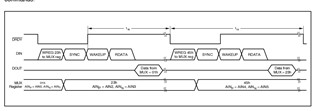
4. We set the data rate 1000SPS, and we measure the input multiplexer Cycling, and the t19 is 1.9ms which is diffenect from the datasheet t19 less than 1.19ms(837Hz);

5. The schmatic diagram for your evaluating:

skh-63568j_20220924a_17.pdf

  • Hi Zhang Liang,

    I was unable to get to this question today, but I will review and get back to you tomorrow. Thank you for your patience

    -Bryan

  • Hi,

    We can't get the accurate samping voltage from the ADC, so pleaes kinldy review the schematic diagram and advise if there are any improve, thanks.

  • Hi Zhang Liang,

    What do you mean by this statement?

    We use the 100ohm resistance for the differential voltage sampling, when input voltage is 1.9554V, the measure voltage from ADC is 1.9550-1.9539V;
    1. Where are you connecting the 100ohm resistance to your circuit? Across a differential input e.g. CH1+ and CH1-? It might help to see a drawing or block diagram of how you have your circuit configured
    2. How are you generating the voltage across the resistor?
    3. What is the absolute voltage at each pin? For example, what is the voltage with respect to ADC_GND at CH1+ and CH1-?
    4. Does the resistor voltage connect through the resistor divider circuit e.g. R629+R630+R631+R632 and R633, which should attenuate your differential input signal by a factor of 10x?
    5. Do you have the ADS1256 buffer enabled or disabled?
    6. Have you performed any calibration on your system?

    We set the data rate 1000SPS, and we measure the input multiplexer Cycling, and the t19 is 1.9ms which is diffenect from the datasheet t19 less than 1.19ms(837Hz);

    How did you determine the timing? Did you use a logic analyzer? If so, can you send me the logic analyzer timing diagrams so I can review?

    -Bryan

  • Hi, Bryan,

    Please refer to below:

    1. Where are you connecting the 100ohm resistance to your circuit? Across a differential input e.g. CH1+ and CH1-? It might help to see a drawing or block diagram of how you have your circuit configured;

    Answer:  For example: the AIN0 is + and AIN1 is -, we series 100ohm both on AIN0+ and AIN1-, the accuracy is very well;

    2. How are you generating the voltage across the resistor?

    Answer: Bettery or High accuracy signal source;

    3. What is the absolute voltage at each pin? For example, what is the voltage with respect to ADC_GND at CH1+ and CH1-?

    Answer:

    1) When direct 100 OHms, input about 1.990V, positive 1.775V, negative about 0.206

    2) When the external input is 10V according to the partial pressure of the schematic diagram, the actual difference end is about 1.980V, the positive end is 5.588V, and the negative end is about 3.610V. But the ADC value is about 3929946 (conversion voltage is 1.9189V) and the actual deviation!

    4. Does the resistor voltage connect through the resistor divider circuit e.g. R629+R630+R631+R632 and R633, which should attenuate your differential input signal by a factor of 10x?

    Answer: Not open;

    5. Do you have the ADS1256 buffer enabled or disabled?

    Answer: It is considered to do 0 calibration, but it is not calibrated when it is only connected to 100 OHms, and the samples are very correct.

    6. Have you performed any calibration on your system?

    We have some waveform for the DSL firl whtich can't linker, so please kindly provide your email and I will send the file to your email, thanks.

  • Hi Zhang Liang,

    You wrote this in your previous response:

    When the external input is 10V according to the partial pressure of the schematic diagram, the actual difference end is about 1.980V, the positive end is 5.588V, and the negative end is about 3.610V. But the ADC value is about 3929946 (conversion voltage is 1.9189V) and the actual deviation!

    If you are applying 5.588V to the ADC inputs, this is well outside the ADC operating range, which is AVDD +0.1V when the buffer is disabled. Applying such a voltage to the ADC inputs could certainly result in large errors. I would suggest reducing the ADC input voltage to within the ADC operating limits. Note that if you have the buffer enabled, the maximum input signal is AVDD-2V.

    You might consider enabling the ADS1256 buffer since you have so much resistance in the input path. You will almost certainly get lots of measurement error due to input leakage effects as well as a resistor divider effect. The ADC input impedance is only ~150kohm with the buffer disabled and gain =1.

    You can send me the waveform via private message by hovering over my name and clicking "Request friendship". This will enable us to communicate in a private setting

    -Bryan

  • Hi Bryan,

    I try to send the private message to you but it is fail, it maybe not identify the .dsl file, so please kindly provide a available way to get the waveform via file.

    BTW, can you help to check if you can download the Baidu netdisk in our company, and I can share the down land linker in the private message.

  • Hi Zhang Liang,

    Did you review the issues I mentioned in my previous post? The large input voltage to the ADC could be the source of your issue, assuming it was described correctly.

    Can you help me understand what waveforms you are trying to send? Can you include screenshots of them instead of the actual file? You can certainly upload JPG, PNG, etc. files to e2e.

    Unfortunately I was unable to download the software you requested due to company restrictions

    -Bryan