This thread has been locked.

If you have a related question, please click the "Ask a related question" button in the top right corner. The newly created question will be automatically linked to this question.

ADS127L11: Calculating maximum time to send conversion data

Part Number: ADS127L11

Hi,

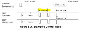
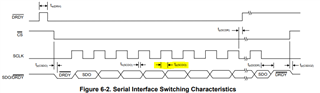
In start/stop control mode, is there a formula to calculate the time between ~DRDY going low (indicating data ready) to the shift register being filled with the next bin of samples? If not, can you please tell me how I can roughly estimate the time between these two events?

Thank you,

Alex

  • Hello Alex,

    DRDY goes low every data rate period, which depends on the OSR setting and the CLK period. 

    t-DRDY=2*OSR*t-CLK

    The next conversion data is updated 2 CLK periods before the falling edge of DRDY.  Total time from DRDY falling edge to next conversion result loaded into shift register (SR), t-DRDY_SR

    t-DRDY_SR=2*OSR*t-CLK - 2*t-CLK

    t-DRDY_SR=2*t-CLK(OSR-1)

    Please keep in mind that the time t-DRDY_SR is when the internal register is updated, but data cannot be clocked out of the device until 2*t-CLK after DRDY falling edge.

    Regards,
    Keith Nicholas
    Precision ADC Applications

  • Thank you for the help Keith.  One other question, how can I calculate the delay from SCLK going low to the conversion bit shifting out?

  • Hello Alex,

    There is no calculation possible for this timing spec.  The propagation delay is due to the internal layout and speed of the internal logic gates, and can vary over temperature, part to part, and lot to lot.  We provide a maximum, worst case time, that covers all of these possible conditions to ensure the data is valid.

    In the case of ADS127L11, the data is clocked out of the SDO pin on the rising edge of SCLK, not the falling edge.  The propagation delay is specified as t-p(SCDO)=19ns for valid data after the rising edge of SCLK.

    Regards,
    Keith