This thread has been locked.

If you have a related question, please click the "Ask a related question" button in the top right corner. The newly created question will be automatically linked to this question.

DAC11001A: DAC Reference configuration issue with nonlinearity

Part Number: DAC11001A

We currently have a PCB with once reference supplying 6 DAC11001A devices on a board.  We only have one sense connection circuit for all 6 of these DACs (there was not room for multiples of these circuits).  We are finding that the DACs without the sense connection are performing in a nonlinear fashion that is outside the datasheets specs.  This is our setup:

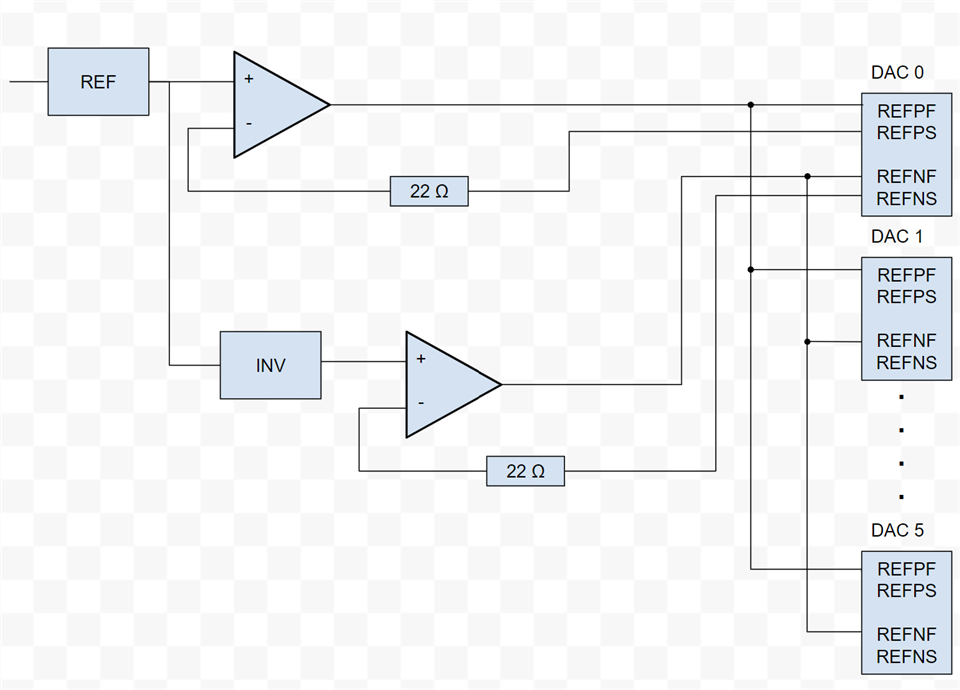
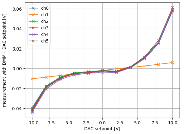
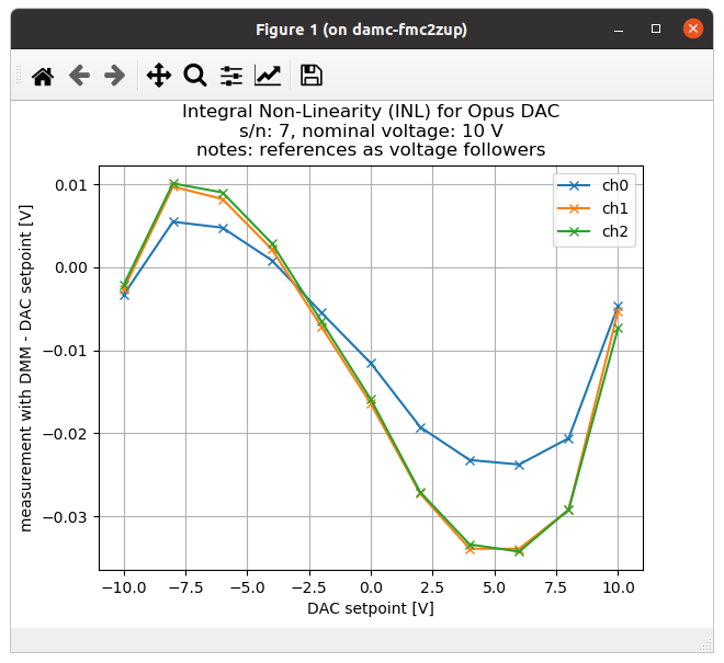
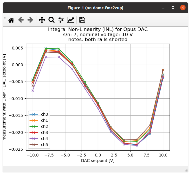
DAC0 is furthest away from the reference in the layout and is connected to the sense circuitry.  We have experimented and found that if we connect the sense line to any other DAC, that DAC becomes the more linearly behaving one and the rest are nonlinear (see image below with test data).  Is there a way that we can configure this to be more linear on all DACs without respinning the board?  Thanks in advance!

  • Hi KB, 

    We will take a look at this and get an answer to you shortly. 

    Best,

    Katlynne Jones

  • Hi KB, this is pretty interesting.  In the plot you are sharing, was the reference buffer connected to the DAC Ch1? Or are you saying that the channels that do NOT have the feedback node is behaving better than the channel that does?

    How much capacitance to you have at each REFxF pin? Adding capacitance might help a little. 

    So when we talk about 20-bit linearity, these reference buffers are essential.  They overcome series impedance from the pin, bond pad, bond wires, and PCB parasitics.  In addition, the reference buffer itself has series output impedance.  The DAC reference inputs have dynamic impedance based on the input code.  So my best recommendation is that you use dedicated reference buffers for each dac.

    You might see better performance than your current setup if you just short the feedback pin to the reference buffer output, and use localized capacitors on each of the REFxF pins.

    Thanks,

    Paul

  • Paul,

    I appreciate the fast response.

    In the plot you are sharing, was the reference buffer connected to the DAC Ch1?

    Yes we have the reference connected to CH 1 in the plot.

    How much capacitance to you have at each REFxF pin?

    We have no added capacitance at each REFxF pin--we will try this.

    So just to be clear--we should try shorting the REFxF and REFxS pin at each DAC and add some capacitance at the REFxF pins?

  • Yes, that is what I am recommending.  You might need to check the reference buffer for stability issues.

    This might give better results than you are seeing, but the optimal configuration would be dedicated reference buffers.

  • Hi Paul--we tried your solution on one channel as well as shorting the Force and Sense outputs at the reference buffer.  Both gave similar results, which was about a 3x improvement:  


    This solution will be sufficient for us until we can re-spin the PCB--thanks for your help!