This thread has been locked.

If you have a related question, please click the "Ask a related question" button in the top right corner. The newly created question will be automatically linked to this question.

ADS1256: Increasing accuracy of ADS1256 reading

Part Number: ADS1256
Other Parts Discussed in Thread: OP07, ADS1261, ADS1261EVM

Hello,

In my project i am using ADS1256 with stm32f4 series and i can able to read the adc data but value is not accurate as input  like its fluctuating more so if anybody have idea on this please let me know 

for more info:

1.ADS1256 with stm32f4 series 

2. Differential 

3. gain 32 so output voltage is 156.25V max

thank you 

  • Hi sagar m,

    Can you please provide more information regarding the issues you are having?

    -Bryan

  • Hello Bryan,

    Thanks for the reply, actually i want to read the pressure sensor data with ads1256 and now i can able to read the ADC value but i want to achieve precision in adc reading because i am dealing with ads1256 with nano volts changes.

    for example,

    1. Now i want to fetch the micro/nano voltage changes  ads1256 is it possible .?? because if i to convert the voltage into Pascal or PSI unit means i need to show even small changes of input pressure its like the pressure value is 3.5786839 PSI or  24674.15691887 Pascal so here once i stop input pressure means value starts decreasing very little because small leakage in pressure so at this point pascal value fluctuating lot like after decimal point the first digit start fluctuating.

    so my point is i couldn't control the pressure value here because in software its just calculation and conversion if any small changes in ADC output then it affects large changes in Pascal because we are multiplying with a large value.( 1 PSI = 6894.76 PASCAL)

    Finally, i am thinking if I can able to read the very minute changes like extremely small changes in adc reading means then can show the variation of pascal value in the 4th or 5th digit of the decimal point so i hope you understand my problem.

    Already i have tried many ways to increase the accuracy like taking the average value and once the device power-up value starts from zero like subtracting with offset value but i couldn't achieve anything.

    please help me to resolve this problem.

    thank you.

  • Hi sagar m,

    Some questions for you:

    1. What is the input voltage range you are using? In other words, what is the output voltage range of your sensor?
    2. What is the reference voltage you are using?
    3. What data rate are you using?
    4. What is the resolution you are trying to achieve relative to the sensor output voltage? For example, "My sensor has an output voltage range of 0-5V and I am trying to achieve 1uV resolution / accuracy"
    5. Do you have the ADS1256 buffer enabled or disabled?
    6. Have you tried using the ACAL feature on the ADS1256? If so, what was the result?
    7. Can you please send us a schematic to review?

    -Bryan

  • Hello Bryan,

    Thanks for the reply, 

    1. My sensor output voltage range (is 0-103mV) so that's why i choose to gain 32 

    2. reference voltage 2.5 V

    3. datarate is 10SPS

    4. resolution is 24-bit and i want it in nano volt or pico volt like i wanted to read extremely small voltage changes in the input because its very useful to show the pressure value variation when i convert it.

    5. Yes i enabled the buffer by writing 0x02 to the status regster.

    6. No I didn't try please explain more regarding this.

    Please let me know if anything required.

    thank you.

  • Hi sagar m,

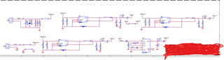
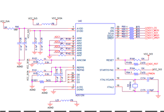
    Some comments about your schematic:

    • The reference voltage appears to be generated by a switching regulator and a resistor divider. Why are you not using a precision voltage reference for this application when noise and DC performance are so critical?
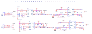
    • You show that the INA has a gain of 100. Are you also using a gain of 32 in the ADC? If so, what is the actual output signal from the sensor (it cannot be 100mV if you are gaining it up by 100 then by 32)?
    • The noise of your system will be dominated by the front-end gain stage because it has a large gain (100). According to the AD620 datasheet, the 10 Hz noise at G=100 is 280nVPP typical. This will effectively be your noise floor, assuming no other noise in the system. So this is the smallest signal you can measure with this system
    • What is the point of the OP07 in your system?
    • I would include LDOs on all supplies to ensure that you don't see power supply noise in your system
    • Do you have separate ground planes on your board? I see a ferrite bead connecting your two ground symbols. Split ground planes can lead to all sorts of issues. You can reference section 12 in the Precision Labs content for more information: https://training.ti.com/ti-precision-labs-adcs

    -Bryan

  • Hello Bryan,

    2. here for 2nd point you said INA has gain 100 but i didn't use op-amp and buffer here due some strange value so i removed those two.

    actually, i couldn't validate the op-amp itself please help me to validate the op-amp and if i used op-amp with gain 100 then in software what gain should be  use.??

    3. Please suggest me comfortable op-amp which can suitable for my application.

    4. op07 acts as a buffer.

    thank you.


  • Hi sagar m,

    Thanks for clarifying.

    You might consider using a different ADC for this application given the very strict noise requirements. The ADS1261 is the next-generation version of the ADS1256, and is our lowest noise ADC.

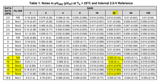
    If you look at the ADS1261 datasheet, you can see that the noise is significantly lower at 10SPS and G=32 compared to the ADS1256. The ADS1261 also already has buffered inputs due to the integrated PGA, so you do not need to enable the buffer as you do for the ADS1256

    It also appears that you are biasing your pressure sensor with +/-5V. The ADS1261 can support bipolar supplies, so you can attenuate your +/-5V excitation voltage to +/-2.5V to power the ADC. This also puts the sensor output common-mode voltage at the midpoint of the PGA common-mode voltage (0V), enabling the widest output swing possible. Ensure that you use clean supplies (LDOs) to provide power to the ADC.

    I think this device will be better suited for your application. You can purchase an ADS1261EVM to test the pressure sensor performance with this new ADC.

    You should also consider reviewing our application note on resistive bridge measurements: https://www.ti.com/lit/sbaa532

    -Bryan

  • hello bryan,

    I wanted to achieve more accuracy and without any fluctuation of adc data so for that, i am planning to use ADS1261 with your full suggestions.

    1. Please tell me that i can use ADS1261 adc to read pressure sensor data with more accuracy and no fluctuation.??

    2. Is there any dev kit available to for ads1261.??

    3. If dev kit is available means please let me know how can i achieve more accuracy and no fluctuation.

    i need your full support for ADS1261 adc reading and achieving fewer noise data read.

    please let me know your feedback.

    thank you.

  • Hi sagar m,

    Resolution and accuracy depend on a lot of system parameters. For example, in your original design you put an instrumentation amplifier (AD620) in front of your ADC such that the amplifier noise will dominate. Or, it could be possible that your sensor is very noisy and it doesn't really matter how high performance the ADC is. So it is not just the ADC that you need to consider, it is the entire system design. This is something you need to determine, I cannot tell you if the ADS1261 will be better or worse. Therefore, I would recommend getting an ADS1261EVM and testing it with your sensor to see if the performance / accuracy is reasonable for your system. There is no way to know if the ADS1261 will be better or the same as the ADS1256 without testing.

    You can find and order the ADS1261EVM here: www.ti.com/.../ADS1261EVM

    -Bryan

  • Hello Bryan,

    thanks for the reply, Ok please have look at the video for what  exactly i need,

    in this video, i am not inputting any pressure so it's just like an idle condition so when there is no pressure you can observe i got 9 .4 mV and in the video, its in nano volts and the total psi value is 0.044 PSI but the value varies or fluctuates after 3rd / 4th  digit in the same way i need pascal to vary for that i need to fetch extremely small changes in ADC is that correct.??

    so for that, i will try to test with the ADS1261 dev kit, and please let me know if any other changes are required in my design to suppress the noise.

    thank you. 

  • Hi sagar m,

    In the video you are showing voltage values on the left. The units on these values says "nvolts", which I assume means nanovolts - is that correct? So you are measuring 0.00000095 nV? But in your last post you said you were measuring 9.4mV, so now I am confused.

    What voltage are those values e.g. "0.00000095" supposed to represent?

    Have you calibrated the sensor? Ideally with no load applied the output should be 0V.

    -Bryan

  • Hello Bryan,

    thanks for the reply, 

    which I assume means nanovolts - is that correct?

    Yes,

    So you are measuring 0.00000095 nV? But in your last post you said you were measuring 9.4mV, so now I am confused.

    No sorry,its actually  0.94mV the same value in the video so i have converted it into nano volt.

    What voltage are those values e.g. "0.00000095" supposed to represent?

    its differential sensor output which is fed into ADS1256 and ADC output is represented as nano volts. is that clear.??

    Have you calibrated the sensor? Ideally with no load applied the output should be 0V.

    i am calibrating the pressure value to convert the Nano voltage value into PSI and not calibrating the ADC output value here its just normal voltage conversion from the raw value of ADC  but the ADC value should be zero as you said but i got some values eventhere is no load i mean there is no pressure.

    that's why in PSI and Pascal get varies even there is no pressure.

    i have tried lot to make it zero but still some fluctuations in ADC reading like in Nano Volts, so is there any solution for this.??

    thank you.

  • Hi sagar m,

    At some point you will need to calibrate the sensor.

    I linked to an app note in a previous post: https://www.ti.com/lit/sbaa532

    Section 5.5 discusses how to calibrate a weigh scale, but the same principles apply to a pressure sensor.

    -Bryan

  • Hello Bryan,

    I am little bit confused like i  have gone through the document i got some info like 

    is that need to set up circuit and connect those four wires of sensor to ADC .??

    Can you please explain it deeply?

    thank you.

  • Hi sagar m,

    The application note provides very detailed information, I am not sure what else I can tell you that the document does not.

    I would review the entire document, especially how a ratiometric reference works and the examples at the end.

    -Bryan

  • Ok Bryan thanks for the info i will read the document and let me know the update.

  • Hello Bryan,

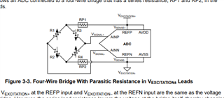
    I have gone through the document, and there is a wheat stone resistance bridge used with 4 wires like for my application, and then positive  and negative out fed to ADC AINP and AINN but i have question here 

    for example  i have differential pressure sensor with pins 

    1. GND

    2. sensor o/p  NEGATIVE 

    3. 5V

    4 sensor o/p POSITIVE 

    so as off now i fed these two sensor output pins to my AD620A op-amp as said in the previous thread  

    and the it leads to ADC.

    and  DP sensor looks like this with 4 pins


     I  think the output comes from the sensor its self-differential voltage which is fed to op-amp and then it leads to ADC. so here how can i use the wheat stone bridge to connect the sensor or how can i calibrate the device i am confused.

    please tell me the way of calibration.

    thank you.


  • Hi sagar m,

    Both ADCs (ADS1256 or ADS1261) accept a differential input directly. So if you purchase the ADS1261EVM you can connect the sensor output directly to the analog inputs on the EVM.

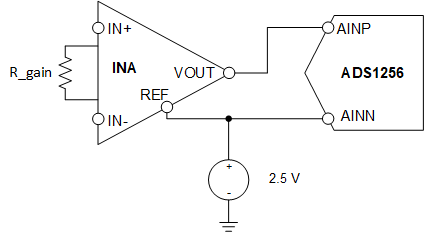
    An INA like the AD620 has a differential input and a single-ended output. The drawing I sent you takes that single-ended output and converts is to pseudo-differential input for the ADC. Again, you will not need to do this if you just apply the sensor output directly to the ADC inputs.

    Please review the calibration section of the document I sent you. This provides step by step instructions for calibrating a resistive bridge sensor. As I stated previously, I am not sure what else I can say that the application note does not. It is pretty comprehensive.

    -Bryan

  • , you will not need to do this if you just apply the sensor output directly to the ADC inputs.

    For the sake of achieving higher voltage calibration, i have used the AD620A, like gain 32 is 156.25mV and i need to calibrate it to 103mV so that's why I have used AD620A. 

    is that the same thing you said.??

    This provides step by step instructions for calibrating a resistive bridge sensor. As I stated previously,

    please don't mind i have silly doubt, like the wheat stone bridge is inside the sensor.?? or i need to make a bench setup of wheat stone bridge.??

  • Hi sagar m,

    To be very blunt, if you are asking these types of questions about your own sensor you might want to stop designing a circuit and start doing a lot more research. These are very fundamental questions that should have been answered long before you put a schematic together, let alone built and started testing a PCB

    The goal you are trying to achieve in this project (nV to pV resolution of a pressure sensor) is very difficult. It requires a lot of background knowledge regarding how the different analog blocks work (amplifier, ADC, etc.), how to calculate noise performance, how bridge sensors work, and how to put all of these pieces together to make a functioning system.

    I would strongly encourage you to step back from this project and start trying to find answers to these questions. I have provided a lot of good information for you to review, including our Precision Labs training material and various application notes. You should also research the sensor you have and try to better understand how it works. You might also reach out to the manufacturer of the sensor for more information.

    -Bryan