This thread has been locked.

If you have a related question, please click the "Ask a related question" button in the top right corner. The newly created question will be automatically linked to this question.

ADS124S08: Time period of Sampling rate

Part Number: ADS124S08

Hello Expert,

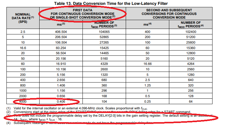
Our customer is using it by setting DATA RATE = 4000SPS, and when drdy is ready, it sends start again to check the repeated sampling period.

It is confirmed as 450us, not the theoretical 250us. Please check what the problem is.

Below is the customer setting, please refer to it, and please guide the necessary items sequentially or source code for the register setting related to the data rate setting.

For your reference,

* Register setting

#define CH1_ACT    ((MUX_AIN0 <<4) & 0xf0) | MUX_AIN5

#define ADS124S08_CMD_RREG  0x20

#define ADS124S08_CMD_WREG  0x40

#define ADS124S08_CMD_START 0x08

#define ADS124S08_CMD_STOP   0x0a

#define ADS124S08_CMD_RDATA            0x12


               wr_data[0]=ADS124S08_CMD_WREG +INPMUX_reg ;

               wr_data[1]=0x02; //number of registers to read or write ?? -1.

               wr_data[2]=CH1_ACT;

               wr_data[3]=0xe0;   /// 1110 0000    -> 111 : 1 · tMOD

               wr_data[4]=0x3e;   /// 0011 1110    ->1 : Single-shot conversion mode,  1 : Low-latency filter (default) , 

                                     ///                      1110 : 4000 SPS


HAL_SPI_Transmit(&hspi3, (uint8_t*)wr_data, 5, 100);

* Check the sampling rate

             if(ADC_drdy==1)   //Falling edge ex interrupt

            {

                                 ADC_drdy=0;

                                 ADC_CS_LOW;

                                 u8a_Flash_tx_data[0]=ADS124S08_CMD_START;

                                 HAL_SPI_TransmitReceive(&hspi3, (uint8_t*)u8a_Flash_tx_data, (uint8_t*)u8a_Flash_rx_data, 1, 100);

                        ADC_CS_HIGH;

          }

Best regards,

Michael

  • Hi Michael,

    I think there is a misunderstanding as to how the device operates.  Table 13 from the ADS124S08 datasheet shows the time for conversion when using the low-latency filter.  Note the areas circled below:

    When in single-shot mode, the conversion is nominally 406us + the default delay of 14 tmod periods which is about 55us.  So the total time after the START command is issued is 406us + 55us which is 461us.

    When operating in continuous conversion mode the first conversion will still be the 461us with the second and subsequent conversion at 250us.  This behavior is shown in the next set of columns to the right.

    Best regards,

    Bob B