This thread has been locked.

If you have a related question, please click the "Ask a related question" button in the top right corner. The newly created question will be automatically linked to this question.

ADS131M02: smaller peak to peak measurement value

Part Number: ADS131M02
Other Parts Discussed in Thread: ADS131M04EVM, , ADS131M08EVM, ADS131M08

Hello Support team,

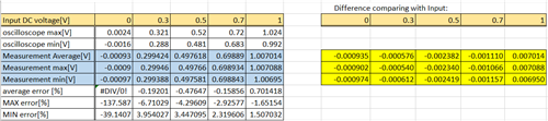
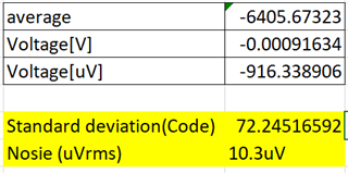
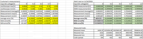
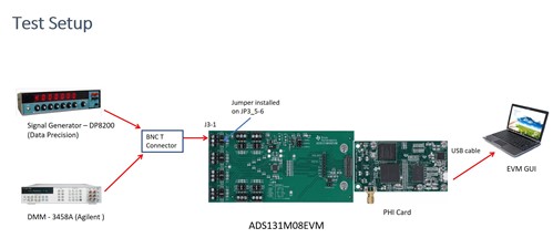
My customer is evaluating 50/60Hz voltage AC signal by using ADS131M04EVM, but, the peak to peak value on ADC result is smaller than measurement. Is this normal behavior of ADS131M02? They use 8kSPS, PGA gain=1, no offset/gain/phase calibration.

Thanks,

Koji Ikeda

  • Hello Koji,

    Can you please let me know how the customer connect the signal to the EVM? Are they using a signal generator? What's the input voltage and what the code they got from the ADC? More information will be very helpful, thanks.

    Best regards,

    Dale

  • Dale-san,

    Let me contact you off line.

    Thanks,

    Koji Ikeda

  •  Koji-san,

    Thank you for providing the data to me. I checked the customer's data especially DC input and calculated the difference between the measurement and the input signal, the difference for each measurement is highlighted in yellow below:

    When the input is 0V, around -1mV was measured. The typical offset on ADS131M02 is +/-175uV, I guess the customer is forcing the signal generator's output to 0V, this is an error mainly from the source. The error in the rest of measurements combines the offset error and gain error together, so I would suggest the customer to do the offset and gain calibration and then check again.

    Best regards,

    Dale

  • Hello Dale-san,

    Thank you for your support. Customer evaluated again without no connection to input CH. Here is the result.

    0A.xlsx

    They assume that this would not come from gain/offset calibration. Under AC voltage measurement with DC bias, if gain is smaller, both min/max value(peak/bottom) of ADC value should be smaller. But their evaluation result shows peak(max) value goes smaller, while bottom(min) value goes bigger. Could you confirm your assumption is correct? And if yes, please show your comment for this opiont.

    Thanks,

    Koji Ikeda

  • Koji-san,

    I checked the data in your new excel file (0A.xlsx) which were taken for grounded input (I believed it's CH3 channel as shown in the EVM board picture in the excel file). I added two lines for standard deviation and noise calculation as shown in the following table:

    I can see the noise from the customer's measurement is around 10.3uV which is a little bit higher than the spec in the datasheet (7.56uV at 8ksps and gain=1 in table 7-1). However, the customer only took 256 samples, so I believe the noise will be lower and close to the spec if more samples can be taken. This shows the ADC is working functionally. Also, I can see 0.916mV offset voltage from the customer's measurement which is higher than typical 175uV offset error spec shown in the ADS131M02/4 datasheet. I will receive an EVM board next week, I can measure it and double check if this is true on the EVM.

    As I showed the voltage difference between the measured result and input signal which was highlighted in my previous post, the higher input signal, the higher difference/error, this is the reason why I thought there is an gain error in the measurement.

    Regarding the customer's concern about test result you mentioned, can you please point out and clarify "their evaluation result shows peak(max) value goes smaller, while bottom(min) value goes bigger"? thanks.

    Best regards,

    Dale

  • Hello Dale-san,

    Do you have any update for your bench test?

    >Regarding the customer's concern about test result you mentioned, can you please point out and clarify "their evaluation result shows peak(max) value goes smaller, while bottom(min) value goes bigger"? 

    Please confirm MAX error and MIN error on Remove offset table in AC(0.576V offset) sheet, which I sent to you offline. max/peak error (%) is higher than min/bottom error(%). They think that if this is caused by gain calibration, max and min error could have same. So they need your comment.

    Thanks,

    Koji Ikeda

  • Hi Koji-san,

    I just got the EVM today, I will do a test on it tomorrow and let you know the result.

    Thank you for your clarification, I will look into the customer's test data and calculation.

    Best regards,

    Dale

  • Hi Koji-san,

    I have done a test with DC input on ADS131M08EVM which is 8 channel version ADC, please see my test data and result in the following table on the right, the table on the left is the customer's measurement you sent to me offline. The customer is calculating the error with this equation:  Max error (%) = 100*(Measured max voltage from code - Measured max voltage on ADC input)/Measured max voltage on ADC input, a similar equation is used by the customer for min and average error calculation. I's using the same equations to calculate the error.

    From my test data, you can see:

    • The offset error I measured on the EVM is 231uV, the offset error specification in ADS131M08 datasheet is 240uV typical. My test result matches the specification in the datasheet. However, the customer got around 900uV error converted from the code which should come from their signal source, and also they got 1.6mV~2.4mV measured by oscilloscope on the input when the signal generator's output is 0V, this is a measurement error from the oscilloscope. The customer can directly short the input on EVM instead of using a signal generator for 0V input.
    • I got very stable error for different input signal, it's around 0.2%. The customer got pretty large error and also it's not consistent for different input. I think the biggest issue is, the oscilloscope the customer used is not accurate and it led to a big measurement error. 

    In summary, a precision signal generator and DMM are needed for the test. Let me know if you have any further questions.

    Best regards,

    Dale

  • Dale-san,

    Thank you for your support.

    Your test data is for DC only, do you have any other data for AC without offset, AC(PGA gain x4) and AC (0.576V offset), too?

    Your summary means the if they measure with precision equipment, the similar accuracy will be available for AC voltage, is their understanding correct?

    Thanks,

    Koji Ikeda

  • Hi Koji-san,

    DC input is a easy way to test the ADC, check and verify the error the customer cared about, the result is not related to input signal. Your understanding is correct.

    I can check it with AC input, however it will take few days for me to use a different setup. Let me know if you want to do that. 

    Best regards,

    Dale

  • Dale-san,

    Customer request us to share your measurement setup and measurement equipment, could you support? Photo or figure is very helpful to understand.

    Thanks,

    Koji Ikeda 

  • Koji-san,

    Please see the test setup below.

    Regards,

    Dale