This thread has been locked.

If you have a related question, please click the "Ask a related question" button in the top right corner. The newly created question will be automatically linked to this question.

ADS124S08: ADS124S08 ESD Diodes on inputs and IDAC pins

Part Number: ADS124S08

Hello,

We intend to conduct EMC testing, which includes ESD on our temperature sensing device which consists of an RTD connected to an ADS124S08.

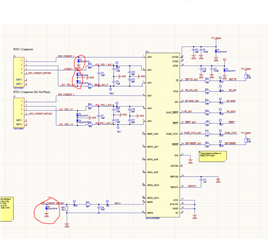
I was wondering if anyone knew the impact of connecting an ESD diode to ADC inputs and IDAC pins like below:

We were looking at using ESD diode: ESD351 1-Channel 30 kV ESD Protection Diode with Low Clamping Voltage in 0402 Package datasheet

Would connecting these diodes to the exposed pins affect our measurements at all? We are using a PT1000 RTD.

Any help is appreciated.

Kind regards

  • Hi Jonathan,

    Adding TVS diodes to the analog inputs is a good practice.  However there are two important considerations.  The first is leakage.  Some diodes have a large reverse leakage characteristic which can be many microamps of leakage that can directly impact the excitation and reference.  The diodes you show have a small leakage characteristic (typical 0.1nA) which is good.

    The second consideration is the clamping voltage.  The clamp voltage may be higher than allowed for the analog inputs.  The absolute input voltage is AVDD + 0.3V.  You are showing 3.3V for the AVDD supply which means that the clamp voltage is greater than the supply.  To prevent damage to the ADC, the input current through the internal ESD structures for the ADC must be limited to 10mA or less.  It would appear that the filter resistors for the reference and RTD inputs will limit the current sufficiently.  However the IDAC pins have no current limit protection.  To prevent damage to the ADC inputs used as IDACs, an additional resistor should be added in series to limit current.

    To understand the method of protection for the IDACs, there is an EOS application note for the ADS124S08.  This application note covers sustained long term overvoltage protection (using much higher current ratings and physically larger diodes).  As this design is beyond fast transients, such as ESD, the requirements for your design are not as stringent but the design principle would be similar for protecting the IDACs from overvoltage by limiting current back through the ADC.

    Best regards,

    Bob B

  • Hi Bob,

    Thank you for your help with this one.

    I am happy that the filter resistances will limit the voltage and current at the input pin when the diode clamps to 6.5V.

    Can you please confirm if my thinking is correct for the IDAC protection?

    For the IDAC pin we have to be no larger than AVDD - 0.4V = 2.9V (As our excitation current is 500 uA)

    Our max voltage at VAIN1 will be 2.3V @ 80 °C (it is very unlikely we will reach this temperature in our application) with a PT1000 (Resistance of ~1300 ohms at 80 °C and reference resistor of 3300 ohms)

    So we have 0.6V of headroom for the IDAC compliance (chosen 0.5V to be safe)

    R = V/I

    = 0.5 / 0.0005

    = 1000 ohm resistor required for a 0.5V drop at 500 uA.

    At a clamping voltage of 6.5V to limit to 3.3V and <10 mA :

    I = 6.5 - 3.3 /1000

    = 3.2 mA

    Any feedback is greatly appreciated.

    Kind regards

    Jonathan

  • Hi Jonathan,

    Yes those values could work, but I don't think you would need to go that large for the Rprotection.  The total voltage drop must be less than AVDD-0.4V for IDAC compliance so the equation (AVDD - 0.4V) less than or equal to IDAC( Rprotection + Rrtd + Rref).  The other piece is clamping voltage - (AVDD + 0.3V) divided by 10mA must also be satisfied. So 6.5V - (3.3V + 0.3V) equals 2.9V requiring a minimum Rprotection of 290 Ohms.

    Now this is all theoretical voltages, current and resistances.100mV may not be enough headroom if for some reason the IDAC current is slightly larger and the AVDD is slightly lower in real world conditions.  So I would recommend a compromise by lowering the Rprotection to some value around 500 Ohms.  This is 1/2 of your calculated value and nearly double the minimum value allowing for a little more headroom when operating in a normal operating condition (without the transients).  In the end it is up to you to weigh the options and make a decision for your system.

    Best regards,

    Bob B

  • Hi Bob,

    Thanks for the advice. I've reduced the resistor to 470 ohms. This will give me a lot more headroom.

    Do you ever place protection diodes on the analog or digital supplies of the ADC?

    Thanks

    Jonathan

  • Hi Jonathan,

    Yes, I have seen this done as some supply sources may have issues back driving current through the source.  I have seen both TVS and zener diodes used for this type of overvoltage protection.

    Best regards,

    Bob B