This thread has been locked.

If you have a related question, please click the "Ask a related question" button in the top right corner. The newly created question will be automatically linked to this question.

ADS1110: I2C General Call response ?

Part Number: ADS1110
Other Parts Discussed in Thread: ISO1540, ISO1640, TCA9535, PCF8574

Hi There,

As per datasheet, ADS1110 is responding to I2C General Call. It, then, logically responds by an Ack to a 00h device address on the bus.

Here is my question:

Does it acknowledge 00h address ONLY if it is the FIRST byte after start signal ?

Configuration:
On my system, ADS1110 and AT24C04 (EEPROM) are connected on the same I2C.

Writing data to AT24C04 requires 3 bytes (1 byte for Device address, 1 byte for EEPROM byte location and 1 byte for data to be written).
When ADS1110 is connected on the bus I'm experiencing strange behavior, cannot write byte value 01h in the eeprom.
Looking into the i2c frame with a scope it turns out that the lsb bit of the data byte is somehow pulled down when it shouldn't.

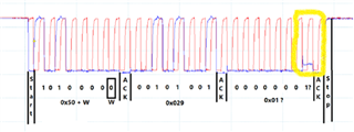
Below is the scope screenshot with ADS1110 connected on the i2C bus and writing 01h in location 29h (AT24C04 address is 50h): look at the lsb of the 3rd byte (yellow):

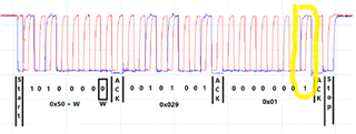
Below , same writing, but ADS1110 is not connected to the bus (ADS1110 is mounted on an add-on board which can be unplugged)):

My question is : Can the 2nd "ack" and the seven following bits (forming together a 00h byte) be understood as a General Call by ADSS1110 ?
This shouldn't because it is not an address byte, but so far that's my only understanding.
any other idea ?

Thanks for Help.

René

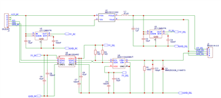
PS:here is the add-on board schematic:

  • Hello René

    Can you share the schematic for the EEPROM?

    I agree that I do not think the ADS1110 is interpreting the data command as a general call. The general call is only when the data is the address byte. 

    I predict this may be related to the digital isolator device, ADUM1250, is there a that you can do a test without this device to eliminate it as the source of the issue.

    Please note that with the holiday, there may not be responses until after the holidays 

    Regards

    Cynthia

  • Hello Cynthia,


    I already made a test without isolator and the problem does not appears.

    I also tried to keep isolator in place while removing ADS1110, problem does also not appears.


    These two test demonstrate that this is the association ADUM1250+ADS1110 which is causing the issue, but none of them is 100% responsible.

    The ADUM1520 has not embedded logic, it just pass signal through, both way for SDA and SCL lines. But it also play the role of amplifier…
     

    You said that you do not think ADS1110 has wrong interpretation of General call. Can you ascertain this point ?

    I’ve ordered some MCP3425 from Microchip and ISO1540 from Ti which are pin to pin equivalent.

    Received MCP3425, no improvement.

    I'm now waiting for ISO1540 (By the way what is the difference between ISO1540 and ISO1640, only  drawn current from 35mA to 50mA ?)

    I will keep you posted on results.


    I’m not allowed to share schematics, but concerning eeprom, there not so much to know:

    • Eeprom is AT24C04
    • Controller is LPC1768
    • I2C bus is controlled via GPIO (P0.28=SCL, P0.27=SDA) and is driven by LPC17xx.cmsis library, very classical.
    • SDA and SCL lines are pulled up to 5Vdc via 1k resistors
    • Distance between controller and eeprom is approx. 3cm (same board)
    • Distance between controller and ADS1110 is approx. 80cm


    Please not that they are other devices on I2C bus (PCF8574,TCA9535, Pressure sensor) and they are all working fine (I suppose because the I2C protocol for those is only 2 byte, address+data) and the issue I’m facing starts from the 3rd byte.

  • Yes, I am certain that the ADC is not interpreting the second byte as a general call. A general call needs to be an address, an address by definition needs to be after a start condition.

    The ISO1540 and ISO1640 are completely compatible, the ISO1640 is a newer device and has better isolation rating and lower supply voltage rating.

    Taking a closer look at the scope shots, it looks like there is some marginal timing performance. It seems that communications on SDA is edge triggered. SDA data should not line up with any SCL edges. An SDA bit should encompass an entire high clock pulse and change state while SCL is low. Are you creating patterns from your host device to simulate I2C communications? this practice is commonly called Bit Banging and is not a good practice. 

    Can you look into your host device to ensure you are using correct I2C timing protocols? From what you shared, you are not using I2C protocol busses, I am assuming 27, and 28 are the pin numbers for the LPC1768, and are only GPIO pins

    You should be using the designated pins that support I2C on your host device, such as Pin 25 and 24.

    Regards

    Cynthia