This thread has been locked.

If you have a related question, please click the "Ask a related question" button in the top right corner. The newly created question will be automatically linked to this question.

AFE4403EVM: Issue in AFE4403 SPI read.

Part Number: AFE4403EVM
Other Parts Discussed in Thread: AFE4403, AFE4400,

Hello,

I am using AFE4403 EVM board, and for the SPI communication with an external MCU (arduino), I remove the registers given inn table 3 of EVM userguide.

I have no issue in write any register, but when I try to read, I get half of the value. For example If I write 8 in register A, I get 4 when I read register A.

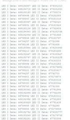
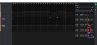
I am attaching a Picture of logic analyzer and the sequence of operation is like this:

Green Box = SPI read Disable (AFE ready to write)

Pink Box   =  Writing 0x8 to address 0xA.

Red Box  =  SPI read enable (AFE ready to read)

Blue Box =  reading 0x4 from register 0xA.   (Half of what I previosly storeed in 0xA)


Code for read:

        
case 'B':{ //AFE Read
      EnableAFERead(10);
     
      Serial.println("#Read from AFE Addr! You can type in Q to quit this state");
      Serial.print("Addr: ");
      while (Serial.available() == 0) {}
      OutputTypeS=Serial.read();
      if(OutputTypeS=='Q'){
        OutputType=OutputTypeS;
        while(Serial.read() >=0){}
      }
      else{
        lowInt=OutputTypeS-'0';
        
        while (Serial.available() == 0) {}
        midInt=Serial.read()-'0';
        
        while (Serial.available() == 0) {}
        highInt=Serial.read()-'0';
        while (Serial.available() == 0) {}
        SUPhighInt=Serial.read()-'0';
       
        SPIval16[0]=1000*lowInt+100*midInt+10*highInt+SUPhighInt;
       
        Serial.print(SPIval16[0]);
        Serial.print("   ");

        receivedVal=AFE4400_Read_Register(10,SPIval16[0]);

        Serial.print("we got:");
        Serial.print(receivedVal);
        Serial.print("\n");
      }
      digitalWrite(SS, HIGH);
   
      OutputType = 0;
      break;
void EnableAFERead(byte cs){
  byte toWrite[3]={0x00,0x00,0x01};
  writeAFERegister(cs,0x00,toWrite);
 }
void writeAFERegister(byte cs, byte thisRegister, byte AFEValue[]) {
digitalWrite(SS, LOW);
  byte addrToSend = thisRegister;
  SPI.transfer(addrToSend);
  SPI.transfer(AFEValue[0]);
  SPI.transfer(AFEValue[1]);
  SPI.transfer(AFEValue[2]);
 }
unsigned long AFE4400_Read_Register(byte cs,byte addrToRead){
  unsigned long result = 0;   // result to return
  unsigned long resultTEMP[3] = {0,0,0};
  digitalWrite(SS, LOW);
  Serial.print(addrToRead);
  SPI.transfer(addrToRead);
  resultTEMP[0]=SPI.transfer(0x00);
  resultTEMP[1]=SPI.transfer(0x00);
  resultTEMP[2]=SPI.transfer(0x00);
  //resultTEMP[3]=SPI.transfer(0x00);
  result = resultTEMP[0]<<16 | resultTEMP[1]<<8 | resultTEMP[2];
  return (result);
  delayMicroseconds(1);
  digitalWrite(SS, HIGH);
}
  • Question #2:

    Moreover, I verify all those steps mentioned in the thread given below and everything is fine but my "TX_CTRL_SUP = LED_DRV_SUP = 4.9V". I am powering the EVM using USB port (J4) from the PC. Is this fine?

    e2e.ti.com/.../2037431

  • Question # 3:

    I am reading data of LED1 and LED2 from register 46 and 47 respectively, so is there anyway to verify that the received data is correct or not and how these code values can be converted into PPG signal?

    And what does it means "Note that this value is inverted when compared to waveforms shown in many publications." mentioned in datasheet of AFE4403 about register 2E and 2F output. Is it means, to converet the received value (e.g. given in picture below) into binary and invert  '0'  into  '1'  and vice versa?

    Sorry, I am asking multiple questions at a same time but I am doing this to save time. So far, I had asked 3 questions. 

  • Hi,

    No problem.

    Since you still have the EVM board, which is good and could be used to validate the SPI communication.

    -----------------------------------------------------------------------------------------------

    Could you

    1. first note down and/or screenshot several SPI errors/mismatch you encounter when you use Arduino?

    e.g. write or read any particular register and do the screenshot for SPI.

    2. Hopefully, you can still reset the EVM back to the factory default when you used it properly with the EVM GUI.

    And, then try to replicate the steps did in 1 on the EVM with GUI and also observe/screenshot the SPI communication.

    3. then you have SPI communication waveforms from both 1(EVM with GUI) and 2(EVM with your host) for A/B testing(comparison) to know where and how the correct SPI should be and what might need to be changed.

    ----------------------------------------------------------------------------

    The screenshot from the EVM with GUI should match with datasheet timing diagram 

    Figure 7-1. Serial Interface Timing Diagram, Read Operation

    Figure 7-2. Serial Interface Timing Diagram, Write Operation

    8.5.2.2 Reading Data

    8.5.2.1 Writing Data

    Thanks

  • Hello, 

    I figured out the SPI read and now I am getting correct values that I had stored previously.

    I am using internal clock of AFE4403 and using AFE clock (4MHz) as a master and using Table 8-2. Clock Edge Mapping to SPI Registers of AFE4403 datasheet for AFE configuration.

    I removed the SPI resisters so I think I can't use the GUI of EVM but I am still using the EVM USB power supply to Power up the AFE4403. I am using external MCU (Arduino uno).

    Now, can you please help me out with Queastion #2 and Question #3 asked above.

  • Hi,

    Please allow us additional 24hr to get back to you.

    Thanks

  • Hi,

    For Question#2 "my "TX_CTRL_SUP = LED_DRV_SUP = 4.9V". I am powering the EVM using USB port (J4) from the PC. Is this fine?"

    "TX_CTRL_SUP = LED_DRV_SUP = 4.9V" are within the datasheet spec range.

    "powering the EVM using USB port (J4) from the PC. " is also suggested by the user guide "plugging in the micro-USB interface cable to the J4 micro-USB connector on the EVM."

    ----------------------------------------------------------------------------------------------------------------

    May I ask do you connect the EVM to PC only? or are there other board or power supply that has any wire connected to EVM in anyway?

    If there are any other wire or power supply or board connect to EVM, I may suggest -

    Disconnect all other external parts/wires/boards that did not come with the EVM, and use user guide 5.1 Power Supply and Table 2 to check/verify the voltages first.

    ------------------------------------------------------------------------------

    Before question#3, please make sure Question#2 are verified and hopefully you were able to use the AFE4403EVM GUI to read some signal or waveform e.g. user guide Figure 46.   <---let's call this Step/Question#2.5

    --------------------------------------------------------------------------------------------------

    For question#3,

    First of all, again, as mention right above, were you able to follow the user guide to do Step/Question#2.5? And, hopefully record and save/store some waveforms in both ADC code and volts.

    Then, after that, you could continue to use your setup/system, AND, try to do the same Step/Question#2.5 with your system(configure the registers values the same as in Step/Question#2.5), and then you could plot and compare the waveform results from Step/Question#2.5 and the data(ADC codes) you got from your system in Question#3 and see whether they are comparable? 

    ------------------------------------------------------------------------------------------------------------------

    It's highly suggested to plot the converted/digitized ADC code to compare.

    ------------------------------------------------------------------------------------------------

    To convert ADC output code, please refer to datasheet

    Table 8-4 shows the mapping of the input voltage to the ADC to its output code. Table 8-4. ADC Input Voltage Mapping

    -----------------------------------------------------------------------------------------------------------------------

    Regarding to "Note that this value is inverted when compared to waveforms shown in many publications."

    I will need to discuss with other engineers before getting back to you.

    Thanks