Other Parts Discussed in Thread: ADS1292
Recently, we would like to use ADS1299 to design EMG acquisition circuit (technical specifications:0~600 μ V, 1~300Hz). I use a 3-electrode mode on the TI's evaluation kit (CH1P as LA, CH1N as RA, and BIAS_ELEC as RL), which can collect ECG signals from human body. It's the first step in the experiment, indicating that we have correctly used the TI's development kit.
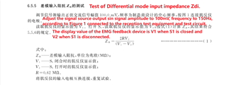
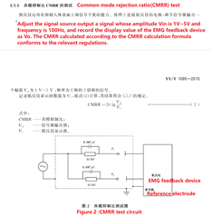
According to the regulation standard, the resolution needs to be able to accurately collect sinusoidal signals of 10μV and 150Hz, and when the input signal changes by 2μV, the amplitude can be distinguished. The differential mode input impedance should be greater than 5MΩ, the common mode rejection ratio index needs to be greater than 100dB.
However, I found that these parameter of ADS1299 maybe can't match the regulation standard.
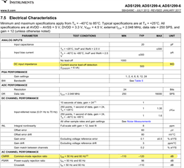
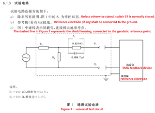
Test according to regulation standard, the signal input was connected to the TI's evaluation kit through the test circuit, and signal output and measurement through ADS1299EEG-FE software. However, the differential mode input impedance value was calculated to be smaller than 5MΩ. The common mode rejection ratio is about 60~80dB. Referring to the data manual, it can be seen that the minimum common-mode rejection ratio is 110dB; typical input impedance is 500MΩ.

Considering that TI's test conditions may be different from YY/T 1095 regulation standard, hope you can help me to evaluate whether it is correct to use ADS1299 to design the EMG acquisition circuit.
1. If the ADS1299 can meet the technical specifications, Are there any details in circuit design that need additional attention?
2. If the ADS1299 cannot meet the technical specifications, Is there any other more suitable circutit or chip recommended to realize the EMG acquisition device ?
Thanks.


