This thread has been locked.

If you have a related question, please click the "Ask a related question" button in the top right corner. The newly created question will be automatically linked to this question.

AFE0064: Photo multiplier signal acquisition DDC264 or AFE0064

Part Number: AFE0064
Other Parts Discussed in Thread: DDC264, DDC232

Hi,

I need to design a acquisition system for a 64 channel Photo-multiplier.  Examples of pulses from the PMT are attached, the signal is across a 330R resistor.  It's a negative going pulse approx 10ns wide with a current of between 100uA and 1000uA.  I was looking at the specs for the AFE0064 and the DDC264.  An application note states that the input bandwidth is in the megahertz range, but I don't see any actual specification for this.  A 1ms integration window is fine for me, but I would like a 100MHz bandwidth in the integrator.

So, do you have a spec for the integrator bandwidth of either of these devices?

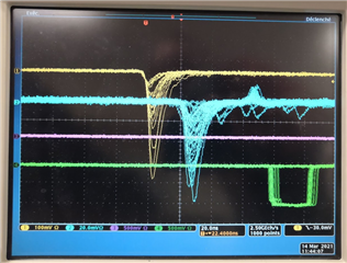
Thank you, Mark McLean

  • Hi Mark,

    The reason that there is no specification for that is that the devices were not originally intended with this kind of operation in mind. So, in a sense, you would be operating them outside their use case... For the same reason, it is difficult for any of us to advice but we can brainstorm or give you some anecdotal data. Nevertheless, the main take away is that it may actually work. 

    DDCs are intended for low frequency applications signals (mainly CT). If the pulse is very fast, the input virtual ground will swing (the amplifier not being able to hold it there) and the input protection back to back diodes may turn on, taking some of the signal to ground. So, there could be an error. Otherwise, the signal will then slowly (compared with the original speed) flow into the DDC and get integrated... as long as the integration time is long enough. Else a portion will be integrated on the next integration cycle (resulting in a temporal crosstalk...). Said that, I believe some folks have integrated +300pC ~5us pulses with some of the older devices (DDC232) and got out pretty good linearity. Those applications were synchronous and knew when the pulse was coming, so, they placed it at the beginning of the integration period. If yours is async then you run the risk of the pulse coming at the end of the integration and most of it being integrated on the next cycle. Besides 232, 264 may still do ok but for some historic reason, 232 has been the choice, so, don't have any reference there. Newer devices do worse in this use case as the inputs were starved of current to save power.

    AFEs on the other side, because of their application, do expect an input pulse... Not ns fast... more like ~us fast. So, this may work as long as you don't saturate the device, which seems fine in your case (10 pC worse case signals). They also have a different input protection, so, when the input swings, it is more unlikely to saturate. I think it is about 0.9V plus diode drop. On the other side, got to keep in mind that they do have a reset period of few us (if the signal comes there, it is gone). But if your application, again, is synchronous, then just aim outside there... Also the input is not virtual ground but some other voltage, so, you'll have to take that into account for your sensor...

    So, all in all, I would try the AFE device and see... Please leave a note later if you ever try for others to learn about it as it is something that comes up every now and then...

    Best regards,
    Edu