This thread has been locked.

If you have a related question, please click the "Ask a related question" button in the top right corner. The newly created question will be automatically linked to this question.

ADS1299: ADS1299

Part Number: ADS1299
Other Parts Discussed in Thread: , ADS1298

Dear Sirs!

Please provide correct description of bits 1:0 of ADS1299, ADS1299-4

I want using DC Lead-OFF detect. In future may be I will use AC Lead OFF

According to datasheet it shall be 0x10 but according to all examples 0x13

Please help to get correct documentation 

Thanks

  • Hi,

    The statement of the question is not so clear. Hope you can clarify more.

    Are you referring to the "pseudo code section"?

    If yes, you are probably correct; the pseudo code section may have mistakes.

    In the meantime, I am guess the following might answer your questions?

    ---------------------------------------------------------------------------------------------------

    To use DC current lead off detection,

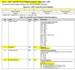
    set LOFF: Lead-Off Control Register (address = 04h) 

    3:2 ILEAD_OFF[1:0] to the current you want based on the experiments and tests and observations

    and

    1:0 FLEAD_OFF[1:0] to 00 for DC lead off detection

    To use AC current lead off detection,

    set LOFF: Lead-Off Control Register (address = 04h) 

    3:2 ILEAD_OFF[1:0] to the current you want based on the experiments and tests and observations

    and

    1:0 FLEAD_OFF[1:0] to any value other than 00 to select the AC current frequency based on the experiments and tests and observations

    and yes,

    you could refer to this e2e post and/or use EVM to validate -

    e2e.ti.com/.../ads1299-why-does-datasheet-example-for-dc-lead-off-detection-enable-ac-lead-off-detection-at-fdr-4

    ---------------------------------

    If above doesn't answer your questions, please clarify what are you asking.

    Thanks

  • Yes, I refer to link mentioned to your answer, but as I see in this link, they recommend to set bits [1:0] to value 3 for DC lead off. It contradicts with datasheet and your answer. What is correct? I know that in ADS1298 it MUST be 3. With ADS1298 I familiar very well. But in ADS1299 it is not clear because these contradictions

  • For DC lead-off detection -

    data sheet -

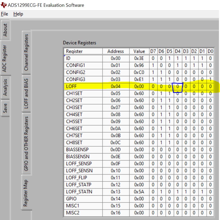
    EVM GUI -

    corresponding register settings -

    bit 4 stay 0 and bit[1:0] are 00.

    Thanks