Other Parts Discussed in Thread: ADC12DJ3200, DAC39J84, LMK04828
Hi All,
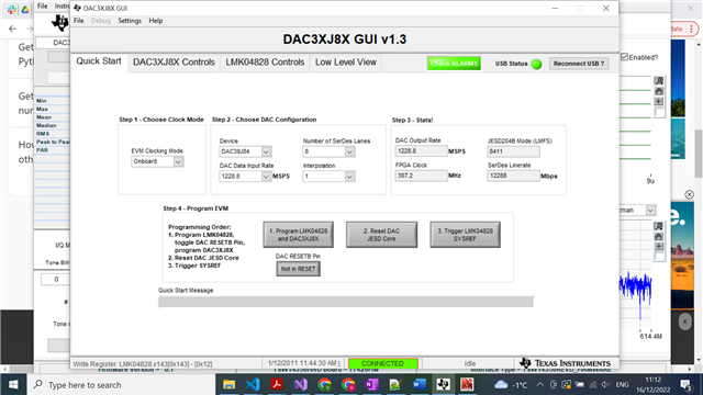
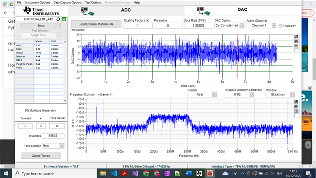
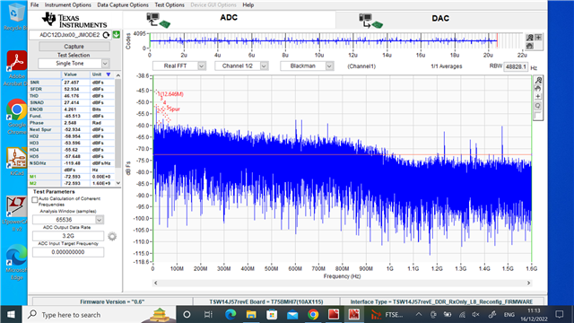
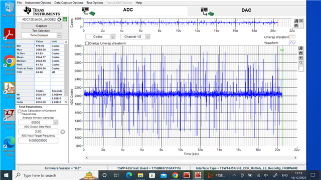
We are sending a pattern ( screenshot attached ) which has a peak at 25 MHz and a wideband with central frequency at 200 MHz as shown in the screenshot using DAC39J84EVM with the DAC settings as shown in the figure attached. The pattern is sent to the DAC by loading an external pattern file (.csv format) on the GUI and the file is attached as well for reference. We send this pattern directly to the ADC12DJ3200 by connecting SMA fibre directly from DAC to the input channel of ADC. The observed frequency spectrum and time domain codes from the ADC are as shown in the figures below. The .csv file of the output time domain are attached as well. The expected output on ADC should have been the pattern sent from the DAC, however there is a marked discrepancy between the two. We checked the output of the DAC on a spectrum analyser and an oscilloscope as well, which shows the same result as ADC, pointing to the fact that the output from DAC is not as is being sent and shown on DAC GUI. Could there be any specific reason for this?
Also, regarding the sampling rate of DAC, which is 2.8GSPS, but when entering through GUI, we are able to access a maximum of 1228.8 MSPS (DAC Data Input rate), how can we access full sampling rate of DAC. Also, is there a way to make the DAC data input rate as 1 GSPS or some integer value as that would be very convenient to our experiment? What changes would we need to do for the same and is this the reason why we are getting such results on ADC ( DAC not being able to sample at 1 GSPS)?
Thanks for your consideration and looking forward to your response.


