This thread has been locked.

If you have a related question, please click the "Ask a related question" button in the top right corner. The newly created question will be automatically linked to this question.

DAC38RF82EVM: How to generate 4.5GHz sinusoidal signal

Part Number: DAC38RF82EVM
Other Parts Discussed in Thread: TSW14J57EVM, , DAC38RF82

Hello!

I want to use DAC38RF82EVM and TSW14J57EVM to generate a sinusoidal signal with a frequency of 4.5GHz. How to do it?

  1. Which clock mode is used? Can the On-chip PLL clock mode or On-board VCXO clock mode be used?
  2. How to set the "DAC MODE" of the software DAC38RF8xEVM GUI?
  3. How to set the "On-chip PLL" of the software DAC38RF8Xevm GUI?
  • Hi Xlaodie,

    These are pretty open ended questions. I will refer to the DAC38RF82EVM user guide to get familiar with some bring up examples with the DAC38RF8xEVM GUI. To truly see a perfect 4.5GHz, the only way will be to use an external clock as the PLL reference or to replace the onboard VCXO with the 100MHz equivalent. As far as creating the tone, I would suggest to use LMF=821 mode (Single DAC, 1IQ pair, 8 Lanes, 6x Interpolation). This will allow an IBW of approximately Fs/6 for flexibility in the data pattern to send. The NCO will be used to mix the incoming data pattern up to the NCO frequency. Something to note here is the maximum NCO frequency is the full DAC sample rate/2. Meaning if the DAC is operating at 8847.36MHz, the maximum NCO value will be 4423.68MHz. To achieve the perfect 4.5GHz without any nearby images, the DAC must sample at 9GHz exactly, as the ffund and (fDAC -ffund) spur will land on top of each other assuming there is a constant data stream from the FPGA. If you are truly just wanting a single tone at a single frequency, you are looking for a DDS and this can be achieved without the FPGA by using the constant input mode. In this mode, the DAC will output a tone at the NCO frequency because the input signal is a constant (0Hz) signal. If you mix 0Hz with an IF, the result will simply be the IF alone, and in the case of the DAC38RF82, the IF is simply the programmable NCO.

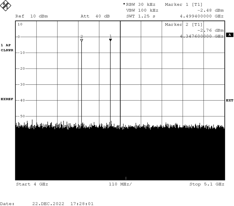
    If sampling at say 8847.36MHz (the maximum possible sample rate without supplying an external signal), then the  ffund and (fDAC -ffund) spur land at the same frequency at 4423.68MHz instead of 4.5GHz. This means that to achieve 4500MHz (ffund=4500MHz), there will be an image at (fDAC - ffund), in this case, the spur will land at 4347.36MHz (which is quite close to 4500MHz) and you would need a high Q bandpass filter at 4500MHz to avoid any unwanted spur. Below is a image of the DAC38RF82EVM running at 8847.36MHz with the NCO set to 4500MHz.

    (This is showing 4GHz to 5.1GHz with MARKER1 set at 4.5GHz and MARKER2 set at the alias tone, 4.3476GHz)

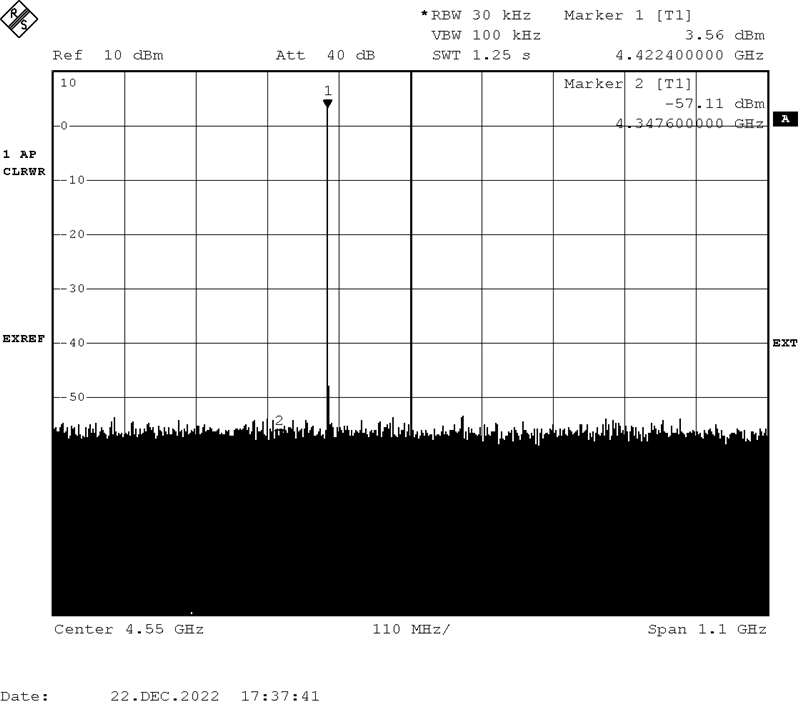
    If you are fine with a single 4423.68MHz output (see below image), then I will create a configuration file for you to use with the DAC38RF8xEVM GUI alone without the need for the TSW14J57EVM.

    Regards, Chase

  • Xlaodie,

    Here is the configuration file you can use to get a single 4423.68MHz output. To load this, simply launch the DAC38RF8xEVM GUI, Click the Reset Button, Click on Load Default once the reset is finished. After the warning message about "Device Initialization Error" pops up, simply close this message. Choose the Low Level View Tab and click on the Load button and browse to the attached configuration file. Once the registers are finished loading, the DAC should be setup and outputting at this frequency. You may have to click on the Auto Tune PLL button if our devices are slightly different.

    DAC38RF82_DDS_MODE_OnlyOnboardVCXO_Fs_8847p36MSPS_Fout_4423p68MHz.cfg

    Regards, Chase