Hi,
I am considering connecting four ADS1015 to one I2C bus. The data sheet states that the ADDR pin can set each slave address with GND, VDD, SCL, and SDA.
1) When is the slave address set? Is it when the power is turned on? I couldn't quite understand from the data sheet how SCL and SDA are judged.
2) There is the following description in the DataSheet, but I do not understand it, so could you explain it as a supplement?
----
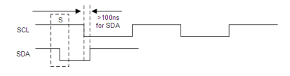
If SDA is used as the device address, hold the SDA line low for at least 100 ns after the SCL line goes low to make sure the device decodes the address correctly during I2C communication.
----
Thanks,
Astro