


Hello. I am designing a PCB for a Strain Gauge measurement system using 2 AD8557 as buffers for the ADS1235 controlled by an STM32. I assembled 20 pcbs, but on 10 of them I get an instability error, the measurements after some time are completely meaningless and replicated in both channels. Since this occured only in 10 PCBs, I assumed soldering issues were involved, but I also suspect that the problem might be in the design/layout. This is my schematic: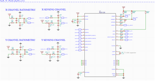
The ADS is configured to work in continuous conversion mode, and I get the readings through DRDY interrupt at 4800 SPS.
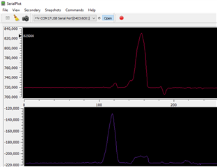
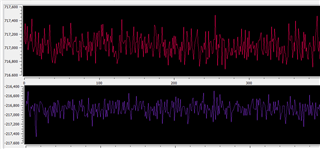
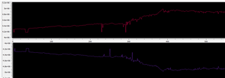
I use the SerialPlot software to visualize the data, where this is what a working system looks like:
(with and without strain)
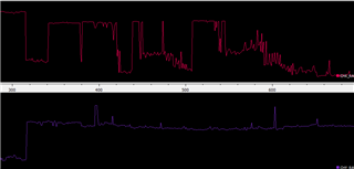
and this is the problem that appears in some pcbs (without strain applied):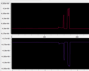
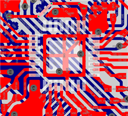 (snapshot of the ECAD software. ADS is in top Layer (L1) while the MCU is in bottom layer (L4), separated by 1 GND and VDD layers)
I hope you can see in the image that the magnitude of this instability is way higher that of the measurements. I concluded that the problem is in the ADS1235 since the error occurs on both channels, and it is driven by 2 separate AD8557s. Sometimes the errors are symmetrical and sometimes not.
I hand-soldered the components on the PCB using hot air pistol at 260C as indicated by the datasheet. Can this problem result from poor layout? The analog traces are separated from the higher speed digital traces, away from the crystal and the PCB has 4 layers with alternating VCC/GND planes, and the component thermal pad is connected to GND.
I would be glad if anyone could provide me with testing procedures to make sure that the ADS is working fine or if there is any way to identify the source of this problem. If there is any additional information I can supply to help, I'm willing to share. Thanks

