This thread has been locked.

If you have a related question, please click the "Ask a related question" button in the top right corner. The newly created question will be automatically linked to this question.

AFE5832: afe5832 external non-uniform mode of tgc

Part Number: AFE5832


hello!

     I have a problem of afe5832.  please help me.  thanks

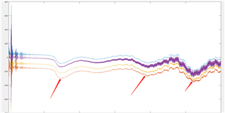
     I select external non-uniform mode to contrl DTGC.  but i find that the dc-biased level of afe5832 will shifted. see picture(arrow)


     base parameter:

     1:  selet external non-uniform mode

     2:  the gain is  12db to 42db,  then total step is 1 to 256step

     3:  positive step is 0, then is 0.125db

     4:  the signal frequency of TGC_SLOPE  is 4Mhz,   ADC_CLK is 80MHZ

    why is the DC-biased level changed? see arrow indication 

  • Hi, 

    We have received your request. Our expert is on leave and will be back by 4th Jan. We will respond by that date. Thanks for your patience. 

    Regards,

    Karthik

  • Hello,

    Thanks for reaching out to us.

    I looked at the waveform you shared and would like some clarifications on the same:

    1. There are 4 distinct waveforms, I am assuming these are of different channels, am I right?

    2. The timescale is not visible in the waveform, can you share the timescale as well.

    3. Can you highlight at which instant are you providing the TGC_SLOPE pulse, for 12dB to 42dB - there will be 240steps, for 12 dB to 44 dB, there will be 256 steps. And also highlight the state of TGC_UP_DN signal.

    In general, there is a residual input offset at the LNA input which can be removed up to some extent by the Digital High Pass Filter. Are you using Digital HPF. If not, can you enable the Digital HPF and see if the issue persists.

    Thanks & regards,

    Abhishek

  • hello thanks

    1: yes, it is 4 channles

    2: timescale

    3: the TGC_SLOPE start at 0 timescale ,  it is uniform,  the signal frequency of TGC_SLOPE  is 4Mhz for 12db to 44db.  TGC_UP_DN is one step at last time.

    4:  we has enable HPF.  if TGC is only  64 step,then DC-biased level of afe5832 output is not changed . 

  • Hello,

    Thank you for the clarification and sharing the waveform.

    I am sorry for the delayed response, I think a small amount of residual offset shall be there and is expected and the Digital High Pass Filter should provide some amount of decrease to this. 

    Also, I can see that the offset is there between the channels. However the waveform you have shared with red arrow indication and multiple places, does that mean that with TGC, you are also seeing the drift in the offset?

    I am also checking with our design team on this, so please allow me some time to gather more information on this offset and offset drift. I will get back to you as soon as I have the required information. You can expect a response from me by Friday.

    Thanks & regards,
    Abhishek

  • Hello Abhishek 

       I am sorry for the delayed reply,  because this account is unused.

      it is two problems.

      1:  There are different offsets between channels, i do not know reseaon.  I hope to resovle this problem in the future 

      2:"does that mean that with TGC, you are also seeing the drift in the offset"  ,yes , i need to resovle this problem first.

    Thanks & regards

  • Hello,

    Understood your concern properly now. 

    Regarding the drift:

    I can see that the there is a low frequency variation in the channel output even with continuously increasing gain. We would have expected the offset to continously increase with tgc gain. It definitely looks like an abnormal behaviour.

    Can you do the following:

    1. Capture this offset variation with constant high Gain instead of variable gain and share the data.

    2. I would like to verify once again about the High Pass Filter. There are two High Pass Filters, 1st is discussed in section 8.3.4 LNA HPF, and other one is in the ADC 8.3.10.3.4 Digital HPF (Page 72) which can be enabled with register settings. Are you using both of them? What is the cutt-off you are using? 

    Can you again check this external TGC mode with the both the HPFs, i really doubt that with the HPF there is still offset.

    Once I get your waveforms for the above cases, I'll share it with my team and discuss it further to reach to a root cause.

    Thanks & regards,
    Abhishek

  • Hello Abhishek

       we will do your advice. it need time.

    because chinese new year,some colleague are out-office now. so we have response after Chinese new year. 

    Thanks & regards

  • Hello,

    No problem.

    Wish you a very happy New Year and have a great vacation.

    Meanwhile, I will also try to take out some time and do the external non uniform TGC mode in our lab and will verify this offset drift.

    Thanks & regards,

    Abhishek

  • Hello Abhishek

       thanks your support.  we have a good news

      we verify the High Pass Filter.  it is some error. we have done new setting. it is ok.

      now it is only one problem, see picture(arrow / 4 channel)


       this point is located at completion of attenuator adjustment

      Thanks & regards,

  • Hi, 

    We are currently handling a large volume of customer queries. We will provide feedback on this by end of this week (Feb 3). 

    Thanks for your patience and understanding. 

    Regards,

    Karthik

  • sorry 

     I only want to delete a  invalid log,    but at the same time delete several log.

  • Hello,

    Sorry for delay. I was trying to get the prior information related to the this glitch when there is a transition from attenuator to LNA.

    Your observations are correct and also aligns with the expected beahvior of the device operation.

    As it turns out, it is a know problem because when the attenuation is changed the the High Pass Filter Corner frequency is also changed accordingly. Hence, near the transition from the attenuator to LNA there is a glitch which is observed.

    In order to avoid this issue, we highly recommend you to use the attenuator in fixed attenuation mode and use use the device. In this way, the HPF corner and the input impedance shall remain the same and this glitch will also not come into picture. 

    I hope this should help.

    Thanks & regards,

    Abhishek

  • Hello Abhishek

       very thank you helping, I have resoved this problem.

    Thanks & regards,