This thread has been locked.

If you have a related question, please click the "Ask a related question" button in the top right corner. The newly created question will be automatically linked to this question.

AMC1306M25: SDFM results are going to saturation after +/-50mV input to AMC1306

Part Number: AMC1306M25
Other Parts Discussed in Thread: AMC1306M05,

Hi Team,

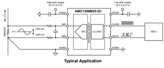
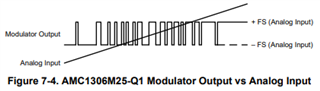
My customer is using AMC1306 -SDFM(F280049) interface for their motor controller application. However, they found that the SDFM results are going to saturation after +/-50mV input to AMC1306. 

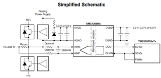
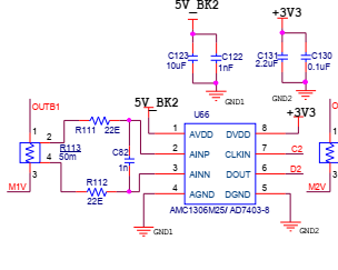
The connections to AMC1306 are done as below:

  1. C122, C123, C130, C131 are not populated
  2. We tried shorting 3 & 4 also (not much improvement)

Based on TI example projects in CCS, we have configured the filter results for OSR=256, SINC3, 10MHz clock. 

Kindly help here.

Thanks,

Jash 

  • Hi Jash,

    The capacitors not being populated should not have an effect on the data output stream, but will affect start-up performance of the device. I recommend populating these components. 

    Pin 3 & 4 should be shorted together as shown in the datasheet in order to ensure that the input voltage remains within the input voltage common-mode limitations of the device and to ensure no damage to the AMC1306. 

    As for saturating at 50mV, please ask the customer to ensure that they have AMC1306M25 (+/-250mV input range) and not AMC1306M05 (+/-50mV input range). 

    Next, please probe pin 6, DOUT, and pin 7, CLKIN, with an oscilloscope when pin 2, 3, and 4 are shorted together to verify a 50/50 1's and 0's density on DOUT.

    Then apply the input voltage and verify the absolute voltages on pin 2 and pin 3 with respect to pin 4 to ensure that +/-50mV is actually being applied to the input. Check DOUT to verify a 58/42 1's and 0's density.

    Please capture these oscilloscope measurements. 

    If these steps do not resolve the issue then the filter settings within the SDFM should be verified. 

  • Hi Alexander, 

    Thanks for your reply. Customer tried implementing all the recommended suggestions but the saturation issue still persists. Please find their comments below.

    1. When we individually test the IC with +/- 250mV at the inputs, we are getting the results as expected. [We removed R111 & R112, and gave DC input directly to AMC1306M25]. We could test upto +/-320mV. Everything seemed OK. 

    2. However when we tested the configuration with 28 VDC pulsating input voltage (with up to 2A DC current) across the 4 terminal kelvin resistor R113, we find the saturation problem.

    a) Is it due to high common mode voltage (28V)? 

    b) Do we have to use ferrite beads in place of 22ohm resistors R111 & R112? What value?

    c) What value do you suggest for c82?

    d) When U66.3 & U66.4 are shorted, we find the current sensing in only one direction.

    e) Could you please give a schematic/ reference/ guide for +/-5A motor phase inline current sensing @ 28 V DC  or any voltage higher than 5 V DC

     3. We wanted to plot the data in MatLab. How to see the SDFM data along with others simultaneously. I have implemented DCL - Data Log module in the code. Where do I see the results?

    Can you please help comment on the issues? 

    Thanks,

    Jash 

  • Hi Jash,

    1. Great, this means that the device is OK and it is a system level issue. 

    2. This violated the input common-mode voltage specifications of the device. This may results in device damage. U66.3 & U66.4 should be shorted to ensure this does not happen.

    a) yes

    b) No, 22ohm resistors are fine

    c) 1n for C82 is OK

    d) How is the high side power supply (5V_BK2, GND1) referred to the current nets (OUTB1, M1V)? If they are not, then this may explain the issue. 

    e) Please see the datasheet for example schematics, there are multiple. For 5A, a 50mohm, 3W shunt can be used.