This thread has been locked.

If you have a related question, please click the "Ask a related question" button in the top right corner. The newly created question will be automatically linked to this question.

ADS1261EVM: Register default setting in not appearing in GUI

Part Number: ADS1261EVM
Other Parts Discussed in Thread: , ADS1261

Hi, 

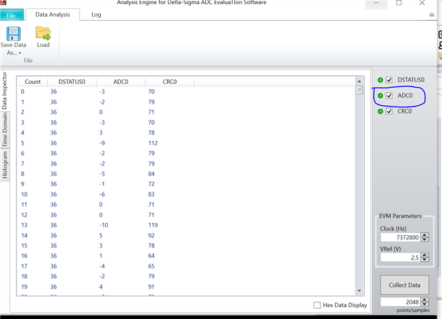
I have successfully installed the driver and GUI software. I can see Hardware connected is showing but default register setting in not appearing. I am using default jumper setting and S1 -5V.


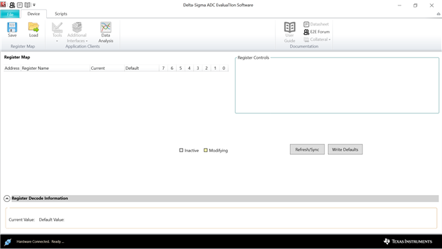
Kindly help me to solve this. 

Thanks,

Ravi Kumar

  • Hi Ravi Kumar,

    Welcome to the E2E forum!  Usually the condition you are seeing is due to the device package for the ADS1261EVM has not been installed or the device package cannot be found in the documents directory.  Did you install both the main application and the ADS1261EVM device package (called ADS1261EVM-DVCPKG found on the ADS1261EVM tools page)?

    Best regards,

    Bob B

  • Thanks Bob, It's working now. But I am not seeing console tab in GUI software as mentioned in software user manual. Where can i see channel output and corresponding voltage in software. 

  • Hi Ravi,

    I'm glad to hear you made progress.  Make sure that you review the material in the ADS1261EVM User's Guide.  As to the Console tab, this is turned off by default.  Information on the Console tab can be found in the Delta-Sigma ADC EvaluaTIon Software User Manual in section 8.  To enable the tab go to the Options -> General menu and enable there.

    To collect data and review conversion results you need to use the Data Analysis.  This tool is described in section 9 of the software user manual.

    Best regards,

    Bob B

  • Hi Bob, 

    Thanks for reply soon and valuable information. I can only see the ADC channel 0 information in Data Analysis tool. The EVM board has input pin AIN9- AIN0, So as per my understanding it should display 9 ADC channel. I am connecting input  2.5 volt to pin AIN7 of EVM. Suggest me  how can i see the ADC value and let me know if  software can convert ADC output  in voltage form also ?


  • Hi Ravi,

    I would highly recommend reading the software and EVM user guides to understand the operation of the EVM and GUI.  There are some ADCs that have simultaneous converters where multiple conversions will be displayed, but the ADS1261 is not one of them.  You will also see in the ADS1261 datasheet that although the ADS1261 has many inputs and combinations there is only one ADC to make the conversion with an input mux in front of the ADC.  So the ADS1261 can only convert one selected input channel at a time and that is why only one result is showing.  Also, the 'ADC0' indicator has nothing to do with the input channel selected.  This is only an indicator from the firmware to the GUI that only one channel data set is being returned called 'ADC0'.  Regardless of the input selected at the mux the data will always be returned as 'ADC0'.

    The Data Inspector tab only shows the result code returned from the ADC.  The data can be viewed as decimal or hex.  The Time Domain tab will show the result in codes or volts with options selected from a drop-down menu.

    Best regards,

    Bob B

  • Hi Bob,

    Thanks for your support. I can configure and operate the EVM now. Kindly let me know if ADS1261 SPI client driver available for Linux kernel.

    Thanks,

    Ravi Kumar

  • Hi Ravi Kumar,

    I'm glad to hear you are making progress with the EVM.  Unfortunately we do not have a Linux driver for the ADS1261.  However there is a Linux driver for the ADS124S08 that could be adapted along with the ADS1261 example 'C' code as additional reference.

    Best regards,

    Bob B

  • Hi Bob,

    I have below observation with imx8mm controller and ADS1261  EVM board.

    Case 1: I have configured SPI clock at 5MHZ and mode 1 and testing with short MISO and MOSI Line of master as you can see the below image.

     Loopback

    Case 2: I am connecting ADS1261 pin to master(IMX8mm) SPI pin and trying to read the command from ADS1261 and getting expected data from ADS1261. Note in this case i have not connected MOSI line of ADS1261 to MISO line of Master.

    case 3 : I am connecting ADS1261 pin to master(IMX8mm) SPI pin and trying to read the command from ADS1261 and getting some glitches and unable to read right data . Note in this case i have connected MOSI line of ADS1261 to MISO line of Master.

    Below are my sample application.

    static const char *device = "/dev/spidev0.0";
    static uint32_t mode =( SPI_MODE_1 ) ;
    static uint8_t bits = 8;
    static uint8_t lsb ;
    static uint32_t speed = 5000000;
    static uint16_t delay;


    static void pabort(const char *s)
    {
        if (errno != 0)
            perror(s);
        else
            printf("%s\n", s);

        abort();
    }

    static void do_msg(int fd, int len)
    {
        struct spi_ioc_transfer    xfer[2];
        unsigned char        buf[32], *bp;
        int            status;

        memset(xfer, 0, sizeof xfer);
        memset(buf, 0, sizeof buf);

        if (len > sizeof buf)
            len = sizeof buf;

        buf[0] = 0x06;
        buf[1] = 0x00;


        xfer[0].tx_buf = (unsigned long)buf;
        xfer[0].len = 2;

        xfer[1].rx_buf = (unsigned long) buf;
        xfer[1].len = 2;


        status = ioctl(fd, SPI_IOC_MESSAGE(2), xfer);
        if (status < 0) {
            perror("SPI_IOC_MESSAGE");
            return;
        }

        printf("response(%2d, %2d): ", len, status);
        for (bp = buf; len; len--)
            printf(" %02x", *bp++);
        printf("\n");


    }

    static void dumpstat(const char *name, int fd)
    {
        int ret = 0;

        /*
         * spi mode
         */
        ret = ioctl(fd, SPI_IOC_WR_MODE, &mode);
        if (ret == -1)
            pabort("can't set spi mode");

        ret = ioctl(fd, SPI_IOC_RD_MODE, &mode);
        if (ret == -1)
            pabort("can't get spi mode");

        ret = ioctl(fd, SPI_IOC_WR_MODE32, &mode);
        if (ret == -1)
            pabort("can't set spi mode");

        ret = ioctl(fd, SPI_IOC_RD_MODE32, &mode);
        if (ret == -1)
            pabort("can't get spi mode");

        if (ioctl(fd, SPI_IOC_RD_LSB_FIRST, &lsb) < 0) {
            perror("SPI rd_lsb_fist");
            return;
        }

        /*
         * bits per word
         */
        ret = ioctl(fd, SPI_IOC_WR_BITS_PER_WORD, &bits);
        if (ret == -1)
            pabort("can't set bits per word");

        ret = ioctl(fd, SPI_IOC_RD_BITS_PER_WORD, &bits);
        if (ret == -1)
            pabort("can't get bits per word");

        /*
         * max speed hz
         */
        ret = ioctl(fd, SPI_IOC_WR_MAX_SPEED_HZ, &speed);
        if (ret == -1)
            pabort("can't set max speed hz");

        ret = ioctl(fd, SPI_IOC_RD_MAX_SPEED_HZ, &speed);
        if (ret == -1)
            pabort("can't get max speed hz");

        printf("spi mode: 0x%x\n", mode);
        printf("bits per word: %u\n", bits);
        printf("max speed: %u Hz (%u kHz)\n", speed, speed/1000);


    }

    int main(int argc, char **argv)
    {
        int        c;
        int        msglen = 2;
        int        fd;

        fd = open(device, O_RDWR);
        if (fd < 0) {
            perror("open");
            return 1;
        }

        dumpstat(device, fd);


         do_msg(fd, msglen);

        close(fd);

        return 0;

    }

    I am not sure why this glitches are coming when i am connecting MISO line of master. But whenever i am trying to read loopback MISO and MOSI line ,it's showing right data.

    Regards,

    Ravi Kumar

  • Hi Ravi Kumar,

    I am a bit confused by what you are saying.  The scope shots look the same and correct to me.  The RESET command (0x06) is transmitted followed and echoed on the second byte of the transfer from MISO as 0x06.  Are you saying that the software is reporting back a different value?  If so, what is being reported back?

    Best regards,

    Bob B