Other Parts Discussed in Thread: ADS5296, ADS5295
This is to post the resolution to the following post - https://e2e.ti.com/support/data-converters-group/data-converters/f/data-converters-forum/1179971/tsw1400evm-frame-clock-error-in-read-ddr-to-file-w-ads5296aevm-frame-clock-and-bit-clock-are-present
Please follow the below steps –
- Install HSDC Pro v5.2
- Install ADS5296A GUI software
- Go to “C:\Program Files (x86)\Texas Instruments\ADS5295_96\Firmware ini Files”. Copy all the ‘ADS5296_...’ files to the following path – “C:\Program Files (x86)\Texas Instruments\High Speed Data Converter Pro\1400 Details\ADC files”
- Connect all the boards as mentioned in here - https://www.ti.com/lit/ug/slau537/slau537.pdf. Use the on board crystal of 80MHz for the initial bring up. Ensure that you are seeing 80MHz clock on Pin 2 of J39 and J40.
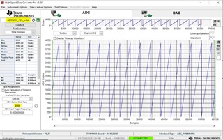
- Open HSDC Pro. Select ‘ADS5296_12b_octal’ from the dropdown. This init_file is used for capturing data when ADS5296 is configured as a 8-ch, 12bit ADC. You will see other files relevant to ADS5296. These can be chosen based on your mode of choice.
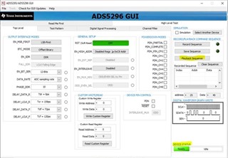
- Now, open ‘ADS5295_96 GUI’ from the following path “C:\Program Files (x86)\Texas Instruments\ADS5295_96”
- From ‘Playback Sequence’, run ‘5296_12b_8ch’ config file. Wait for ‘Device Status’ to show ‘Ready’
- Apply ramp test pattern from the ‘Test Pattern’ tab. Wait for ‘Device Status’ to show ‘Ready’
- Set 80MHz as output data rate and then capture