Because of the Thanksgiving holiday in the U.S., TI E2E™ design support forum responses may be delayed from November 25 through December 2. Thank you for your patience.

This thread has been locked.

If you have a related question, please click the "Ask a related question" button in the top right corner. The newly created question will be automatically linked to this question.

ADS1115: Need help for measuring 50Hz AC current with ADS1115

Part Number: ADS1115
Other Parts Discussed in Thread: REF5020, ADS1015

Hello Sir,

This is the first time I work with ADS1115 16 bits ADS so I need some help.

My aim is to design a high precision current meter using ADS1115 and current transformer. I have read the technical documentation but I am a bit confused about the following issues. Here is my draft design
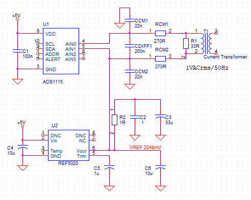
For decreasing the Common Mode error, I choose the differential configuration

Because the output impedance of the current transformer is quite low, I don't use a buffer at the inputs of ADS1115

For measuring AC voltage across the burden resistor R1, which is 1V RMS maximum, I move the  input signal into the range of the ADC by using REF5020

The Rcm1,2 are high accuracy (0.1%) and Ccm1.2; Cdiff1 are all 5% NPO capacitors.

At this time, every thing seems to be OK, but there are some issues that make me confused, as below:

- The documentation says we need to choose the cutoff frequency of the RC filter some where around 10 times the sample rate that should be 860sps (8.6KHz). Because I am about to measure 50Hz signal, what would happen if I choose much lower cut off frequency (say 4KHz)?

- The sample rate of ADS1115 is a bit low. Is 860sps good enough for sampling 50Hz signal (17 samples over a signal cycle)?

- C6 is added for maintaining the stability of the VREF 2048mV as suggested by the document of REF5020 but it changes the cut-off frequency of the CM filter, so should I remove it?

I am looking forward to hearing from you

Thank you and best regards,

Tuan Tran

  • Hi Tuan Tran,

    Welcome to the E2E forum!  The ADS1115 is an oversampling ADC with a digital low-pass filter.  So you really don't need a lower cutoff filter.  I would also suggest that you recalculate your filter cutoff.  The cutoff filter for the differential input is 1÷ (2 × π × (RCM1 + RCM2) × CDIFF1).  As you increase the input filter values you will also increase any analog settling time.

    As far as sampling frequency, by Nyquist theorem you should sample at least twice the frequency of interest.  The actual sampling frequency is the modulator rate and is 250kHz.  The output data rate is 860sps.  The output data rate is the modulator data followed by the low-pass digital filter of the ADC.  Figure 21 in the ADS1115 datasheet shows the filtering characteristics for 8sps.  At 860sps the first filter notch would occur at 860sps and the 3dB filter cutoff would be very close to your frequency of interest.  So you would need to experiment to see how this would work for you.

    C6 is required for the stability of the reference.  It will oscillate if not installed.  I would suggest moving the bias to the other side of the filter resistor.

    Best regards,

    Bob B

  • Dear Bob Benjamin,

    Thank you very much for your quickly reply.

    I will adjust my design as your suggestion.

    For me, there are some uncleared issues that need to be clarified:

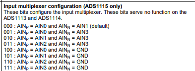
    The document says that AIN0 and AIN1 can be measured differentially to AIN3. I suppose I could use 2  differential inputs and 1 common mode input (AIN2) "concurrently". In this case, I think the process would be as follows:
    - Sw0 is ON, Sw3b is ON for measuring the first differential input (AIN0 and AIN3)

    - Sw0 is OFF, Sw1a is ON, Sw3b is ON for measuring the second differential input (AIN1 and AIN3)

    - SW1a is OFF, Sw3b is OFF, Sw2 is ON, Swgnd is ON for measuring the common mode input (AIN2 and GND)

    - Sw2 is OFF, Swgnd is OFF, Sw0 is ON, Sw3b is ON for measuring the first differential input again, and so on.

    Is the process like this?

    If yes, can the transition of AINn from 2048mV to GND and from GND to 2048mV cause any effect on the accuracy or measuring time of ADS1115?

  • Hi Tuan Tran,

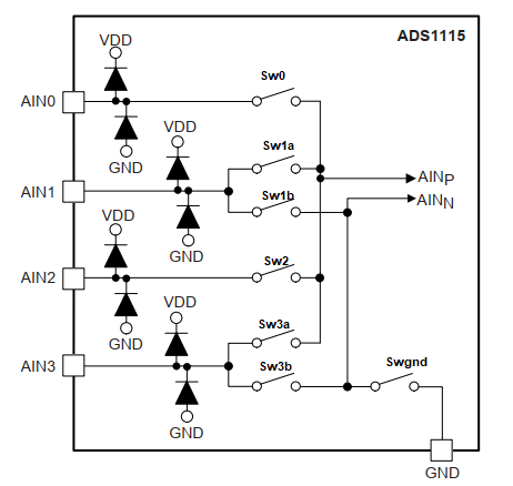
    The available combinations for the input mux are give in the ADS1115 datasheet as follows:

    So the combinations you have proposed are valid.  Just to be clear, the input combinations can not be converted at the same same time (concurrently) but can be measured sequentially (one after the other).  So taking three measurements at 860sps will lower the overall throughput to 1/3 (approximately 286sps maximum for each channel).

    The ADS1115 is single-cycle settling, which means each conversion is valid.  However, there could be analog settling which may add some delay.

    Best regards,

    Bob B

  • Hi Bob,

    Everything is crystal clear for me now. I really appreciate all the help you have given me.

    Armed with all that new knowledge, I feel quite confident to practice and experiment.

    I will come back with the results or if I have any more questions.

    Best regards,

    Tuan Tran

  • Hi Bob,

    Here are some results from the circuit.

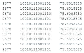
    I measure a fix voltage at the output of a voltage divider which its input voltage is from the REF5020, and here are the results:

    The first column represents the value read from ADS1115, the second one is in binary format and the last one is voltage value.

    The ADC is set at single ended, continuous mode, 16x gain for maximum resolution.

    Measuring by Fluke 179 DMM, the result is 75.7mV, so the difference is about 0.1mV, but I am not sure because the DMM only shows one digit after the decimal point.

    It looks like my results are not so good because I use the power supply from the Arduino board for ADS1115 without isolation.

    I think I should use differential mode to increase the measurement accuracy.

    If you have any suggestion, please kindly let me know.

    Thank you and best regards,

    Tuan Tran

  • Hi Tuan Tran,

    I don't think you will gain further accuracy as I think you most likely are in the range of accuracy of your voltage divider and the DMM capability.

    Best regards,

    Bob B

  • Dear Bob Benjamin,

    I am not so sure that I understand how to configure the ADS1115. In my mind, the continuous mode of ADS1115 means if I configure it in this mode and the sampling rate ís 860SPS, I will get a steady 860Hz pulse train out of the ALERT/RDY pin.

    Is that right?

  • Hi Tuan Tran,

    The default action of the ADS1115 is not to trigger the ALERT/RDY function and must be configured properly to do so.  The ALERT/RDY pin requires a pullup to the supply as the pin is an open-drain output.  Also the HI and LO threshold registers need to be configured correctly as specified in the datasheet in section 9.3.8.

    • To indicate a low-high-low pulse at the end of the conversion period set the CONFIG register COMP_POL bit to '0' , COMP_QUE bits to '00'
    • Set the LO_THRESH register to 0x7FFF
    • Set the HI_THRESH register to 0x8000

    If the the CONFIG register is also set to continuous conversion mode and data output rate at 860sps, then when conversions are started you should see a 8us pulse after the completion of every conversion.  

    Best regards,

    Bob B

  • I have just tested the ADS1115 in continuous mode, 860SPS and it has been working well. Thank you for your information.

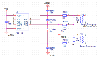
    Now I would like to measure 2 differential channels sequentially (AINp=AIN0, AINn=AIN3 and then AINp=AIN2, AINn=AIN3) and here is the circuit:

    AIN1 is used for another single ended channel, AIN3 is common input for the 2 differential channels and the combination of RCM3 and CCM3 is the RC low pass filter for getting rid of CM noise on the common input. In my mind, this seems to be OK, but I really appreciate if you let me know what is your opinion.

    Regards,

    Tuan Tran

  • Hi Tuan Tran,

    It is difficult to tell what interactions might take place between the two transformers and the capacitance associated between them.  I would suggest simulating the circuit in your favorite circuit simulator and probe to see what may happens if there is shifts in voltage/current/phase.

    Best regards,

    Bob B

  • Dear Bob Benjamin,

    I have just finished testing ADS1115 in differential continuous conversion mode, and here are the results:
    - When measuring DC voltage, the accuracy seems very good

    - When measuring 1V AC 50Hz and calculating the RMS voltage, the calculated results are far from my expectation (the calculated RMS voltages swing around 974mV vs 1004mV measured by Fluke 179 DMM).
    After carefully analyzing the results, I realized that I can't achieve any more accuracy because the sampling rate of the ADC is quite low even though ADS1115 is configured at the maximum sampling rate.

    So I think I can improve my design by using ADS1015 with higher sample rate but lower resolution. Do you think I can directly replace ADS1115 by ADS1015 with some tweaking in the code?


    Hope you can help me with the issue.

    Thank you and best regards,

    Tuan Tran
  • Hi Tuan Tran,

    The waveform appears to be a good representation.  What is the configuration for the full-scale range that you are using?  How are you making the RMS calculation from the data?  Where are you measuring with the DMM?  You should be probing at the same point as the ADC is seeing the input voltage which is directly at the input.  Also remember that the DMM has accuracy limitations too.  Also, what is the final schematic you are using?

    As the ADS1115 does have a digital low-pass filter, it is possible that some of the signal is filtered out even at 860sps, so you could try using a higher bandwidth device like the ADS1015.  The devices are equivalent with the same pinout and configuration except the ADS1015 is 12-bit output with the faster sampling speeds.  As an alternate test before changing devices out I would look to see if there are significant differences between the output at 475sps and 860sps.  Also you could try different gains as well.  Changing out devices without knowing what is happening may not get the improvement you are seeking.

    Best regards,

    Bob B

  • Hi  ,

    Here are some more details about my above results:
    - The full-scale range is selected for the best resolution, meaning it's just only barely larger than the range of the measuring signal.

    - The RMS is calculated by calculating mean of the sum of the squares of measured data, then taking the square root. There were no DC level in the measured data, because I measured in differential mode between AIN1 and AIN3. The RMS value calculate by my code and the one calculated by Excel were identical.

    - I checked the result by measuring the differential voltage between the 2 input pins AIN1 and AIN3 with the DMM, so the result couldn't be affected by the RC filter.

    - The source of the 50Hz 1Vrms AC voltage is a digital wave form generator, the measured value taking by Fluke DMM was 1004mVrms and as I known before, my DMM is quite accurate.

    - My friend has a a Fluke 5522A multi-product calibrator, so I am going to send my DMM to him to check its accuracy.

    I have replaced the ADS1115 by ADS1015 and try to finish coding for better accuracy, but it turned out that ADS1015 can not sample at any rate higher than 475SPS, as I measured the sampling rate by oscilloscope, with Adafruit library. I have to find another library instead.

    Thank you for your very detail advise.

    Regards,

    Tuan Tran

  • Hi Tuan Tran,

    I think that possibly the library you are using may also be the issue with the ADS1115.  It would appear that the capture rate from the ADS1115 is also limited to 475sps.  The slower data output rate does affect the passband of the digital low-pass filter.  It is for this reason I wanted you to try various different data output rates to see if this could be an issue.

    Also it is not clear if every data point is being captured based on end of conversion (ALERT/RDY) or if there is some form of timer being used.  You might want to verify this in the code library as well.

    Best regards,

    Bob B

  • Hi Bob Benjamin,

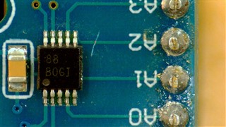
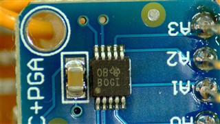
    I have just had my DMM checked by Fluke 5522A multi-product calibrator and the results show that the DMM accuracy is very high. So the low accuracy measuring results mentioned above are not easy to interpret. I am thinking about counterfeit parts so I include here the picture of my ADS1015 and ADS1115. Can you help me to check the package marking?

    Because I would like to achieve the accuracy of 1% or better, I may have to buy ADC's directly from TI to prevent the fake products.

    Thank you and best regards,

    Tuan Tran
  • Hi Tuan Tran,

    I'm not sure which picture is supposed to be for the ADS1015, but there is clearly no device with the ADS1015 marking.  The top picture is missing the logo and the bottom picture looks close, but the marks and physical package do not match examples that I have.  At this time I would suspect that both devices are counterfeit.

    It is always best to buy devices direct from TI or through an authorized distributor.  Due to device shortages, we have seen a number of counterfeit devices showing up and that is always a risk when buying through a brokered source.

    Best regards,

    Bob B