A related question is a question created from another question. When the related question is created, it will be automatically linked to the original question.
If you have a related question, please click the "Ask a related question" button in the top right corner. The newly created question will be automatically linked to this question.
ADS52J65: Differential Input Resistance and Capacitance?
Part Number: ADS52J65 Other Parts Discussed in Thread: TINA-TI
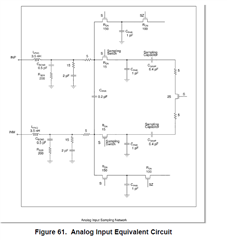
Can you please tell me the input differential resistance and capacitance for this ADS52J65 ADC? I need to set up a Bessel filter at the input, so I need to know what the input looks like. Thank you.
I calculated, with this circuit, an input resistance of only 9.88 ohms. That can't be correct. All these Rs are very small. Do they mean these to be x1000?
You gave me the input circuit instead of the value. When I look at the input circuit, and I short all the capacitors and inductors (for AC), i get very low input resistance (approximately 10 ohms). That can't be correct. Normally input resistance of ADC about 1k ohm. I am designing a Bessel low pass filter to place before the inputs to this ADC. The corner frequency would be 40-45Mhz.
Firstly, I disagree with your analysis. The AC impedance of an inductor (L x jw) is 0 at low frequency and infinite at high frequency. The AC impedance of a capacitor (1 / (C x jw)) is infinite at low frequency and 0 at high frequency. So, if you want to find the impedance of a circuit at very high frequency, you open the inductor and short the capacitors. If you follow your analysis with this modification, you will find the ADC input impedance to be infinite at very high frequency.
But, I am not sure how finding impedance at very high frequency is helpful for you. The input network has a corner frequency that is higher than 500MHz which is expected for a high speed ADC. Instead, why don't you find the the input impedance of this network for the middle of your operating range, say at 20MHz. You design your filter for this range and then see how the frequency response looks with your designed-filter + ADC input network. Does that make sense?
To find the input impedance across frequency, you can hook up the above network (or a single-ended version of the above network) in TINA-TI or PSPICE and apply an input current source with AC-amplitude = 1. Then, if you run AC analysis and observe the input terminals, you will see impedance curve across frequency.
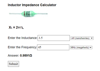
There isn't much impedance on this inductor at 45Mhz. So in the range I am concerned with its essentially a short circuit. Its a nanohenry.
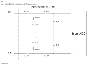
I see this elsewhere on your site: It differs somewhat from the datasheet. Seems like it this is it, you guys would be able to give me a number. Why do all other ADC datasheets have a number? Am I missing something? Thanks for the help Karthik.