This thread has been locked.

If you have a related question, please click the "Ask a related question" button in the top right corner. The newly created question will be automatically linked to this question.

ADS114S06: CMRR vs frequency graph

Part Number: ADS114S06


Any idea where I could find the CMRR vs frequency graph of the ADS114S06 differential input?
Also, the same for the PSRR of the internal 2.5V reference?

The datasheet only mentions values at DC or at 50/60 Hz.

I have an application where a bridge sensor is being excited by the 2.5V internal reference of the chip and read with PGA enabled and set to 32 gain.
We have issues with common mode RF noise in the 61000-4-6 test appearing in the output of the ADC. This occurs between 40-80 MHz.
It appears as a sudden offset shift at certain noise frequencies.

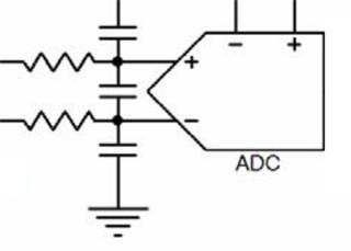
We have this kind of a low pass filter circuit at the sensor interface, but I'm considering eliminating the series resistances and common mode capacitors to improve CMRR.
Problem is, I can't find the actual CMRR at those specific frequencies in order to decide whether I'd have to add an external common mode choke.

  • Hi Gaurav,

    So far I have only found the data collected for the responses shown in the datasheet.  I will update the thread if there is any additional information available.  Passing the IEC tests can always be a challenge.  Depending on the filter values you are using, the common mode caps can be an issue due to phase imbalance creating a difference voltage.  You also need to make sure that the differential cap always dominates over the common-mode caps.  The value difference should be at least 10X greater for the diff cap.

    I wouldn't remove the resistance completely.  This would mean the RFI voltage would be unopposed to the ADC inputs.  This can also show as an offset if the ESD diodes conduct.

    TI will be conducting some of the IEC tests including the 61000-4-6 in the coming months as we realize that passing these tests is critical for our customers.  The lessons we learn in our testing will allow us to better suggest options for passing.  Unfortunately that doesn't help you at this time.  I can suggest that it is important that the cabling be shielded and properly terminated for best results.  We have also seen some success with adding ferrites in series with the input prior to the filter resistors.

    Best regards,

    Bob B

  • Dear Bob, 
    Thanks for the response. 
    What values would you recommend for the resistors? 200ohms? We are currently using 1k ohms. 
    Also, would they need to be matched resistors or would 0.1% tolerance individual resistors be good enough? 
    Would the ferrites still work if I eliminate the common mode capacitors?  
    Also, would those need to be matched too?
    Or would I just be better off putting in a common mode choke in their place?
    Finally, what termination would you suggest for the bridge wires? They're currently far away from the noise source and hence, unshielded and soldered directly onto the PCB pads. I strongly suspect the noise is conducted to the bridge through the bridge excitation (which runs relatively closer to the noise source) rather than being coupled to the bridge output. 
    Regards, 
    Gaurav 
  • Hi Gaurav,

    I apologize for the delayed response.  I was not able to find any additional information.  It is difficult to be specific on recommendations.  If you are using a resistive bridge, the resistance will combine with the series filter resistance.  200 Ohms seems reasonable as charge will move more quickly.  You should not need matched resistors as 0.1 % should be good enough.  

    As to ferrite recommendations, just today we were talking about experimentation using ferrites but at this time no specific recommendations on usage.  What we have seen others use is ferrite surface mount beads with 1k resistance at 100MHz in series with the input filters between the bridge wiring and the filter resistors.  As I mentioned in my previous post, the common-mode filters should not be dominate.  In other words the differential cap should be 10x greater in value than the common-mode caps.  As to whether or not these combinations are worthwhile requires experimentation.  What I have used as a quick check in the past is walkie-talkie (portable RF transmitters) to run some tests that do not require a testing lab.  The results are not precise but do help in determining if you are headed in the right direction with your changes.

    You mention the excitation as being a possible source of the noise pickup as opposed to the bridge output wiring.  That is definitely a possibility.  How are you actually using the reference?  Are you actually making the measurement ratiometric by returning the bridge voltage excitation back to the reference inputs on the ADC?  Or are you just using the register setting to use the internal reference?  Having the external reference input connection will allow additional filtering at the reference and the measurement more closely following the inputs.

    Best regards,

    Bob B

  • Dear Bob,

    I have the input of the bridge between REFOUT and AVSS and use the register setting to use the internal reference with only the recommended 1uF cap between REFOUT and REFCOM.


    I did this due to the Vref being both more temperature stable and having better load regulation than simply connecting the bridge to AVDD and AVSS.
    At the time, I also hoped that the PSRR of the Vref circuit would improve any noise rejection from the power supply, but I suppose the same result would be achieved in the ratiometric measurement to REFN0/REFP0.

    I have achieved better noise performance by removing the common mode caps and applying AVDD/AVSS to the bridge inputs and measuring ratiometrically. 
    However, I have made enough other changes that I am not confident that the resulting improvements were solely because of aforementioned changes.

    However, I suppose I can conclude that my issue is solved. Thanks for the help.

    Regards,

    Gaurav.