This thread has been locked.

If you have a related question, please click the "Ask a related question" button in the top right corner. The newly created question will be automatically linked to this question.

ADS1115: Questions about ALERT/RDY pin

Part Number: ADS1115
Other Parts Discussed in Thread: TXB0102, TCA39306, TCA9406

Hi,

I have a few questions about configuring the ALERT/RDY pin in the PCB design?

If an MCU operating at 3.3V is used to control an ADS1115 operating at 5V, does the voltage of this pin need to be reduced to meet the requirements of the MCU?

If I need to step down the voltage on this pin, would the TXB0102 be suitable for this, or is there any other recommended level shifter?

Will the sampling work without this pin?

Best regards,

Will

  • Hi Will,

    It is not required to use the ALERT/RDY pin for the ADS1115 to function, but it can be useful if the comparator function is needed or if you want to use as the signal to the microcontroller that a conversion has completed and is ready to retrieve from the ADC. 

    The SDA and ALERT/RDY pins are open drain.  The SCL is a digital input only.  The specifications for the pins would follow the Vih and Vil as given in the datasheet.  Vih is specified as VDD*0.7V and for 5V this is equal to 3.5V.  3.3V I2C supply does not meet this requirement.  Check to see if your microcontroller is 5V tolerant at the inputs as in this case you could use 5V as the pullup voltage.  Otherwise a level shifter would be appropriate for mixed voltage levels.

    The TXB0102 is a bi-directional level shifter but can be problematic when used as a level shifter for I2C due to the internal resistance within the device.  A couple of better options would be the TCA9406 or the TCA39306.

    Best regards,

    Bob B

  • Hi Bob,

    Sorry I have three more questions?

    Can the TCA9406 also be used to shift the voltage on the ALERT/RDY pin?

    Will the ripple of the supply voltage affect the resolution? Power for the ADS1115 will be provided by a boost converter.

    For positive voltage measurements, is it necessary to use differential mode if the noise is as low as possible?

    Best regards,

    Will

  • Hi Will,

    Can the TCA9406 also be used to shift the voltage on the ALERT/RDY pin?

    The TCA9406 is a 2-bit device so only two channels can be used in this case (SDA and SCL).  The ALERT/RDY is an open drain output requiring a pullup resistor on the output.  If the pullup is to 3.3V, the functionality to the microcontroller should work just fine.

    Will the ripple of the supply voltage affect the resolution? Power for the ADS1115 will be provided by a boost converter.

    It is possible that the ripple might add noise.  It is recommended that any switcher output be followed be followed by an LDO.

    For positive voltage measurements, is it necessary to use differential mode if the noise is as low as possible?

    I'm not totally clear as to what you are asking.  The ADC can only measure within the range of the supply (which means all input voltages must be above ground) and will always measure differentially (that is with AINP with respect to AINN.  The ADS1115 can measure AINP relative to AINN and the result code will be in binary two's complement.  If AINP is higher in voltage than AINN, the the output codes will be positive from 0 to 0x7FFF.  If AINN is higher in voltage that AINP the output code becomes negative from 0xFFFF to 0x8000.  All input voltages to the input pins must be between VDD and GND.

    If AINN is connected to ground (or the mux input is set to measure relative to ground) then this is considered to be a single-ended measurement and only positive codes will be available and the conversion result is no longer 16-bits but rather 15-bits.

    Best regards,

    Bob B

  • Thank you for your reply.

    Sorry, I have a few more questions?

    In my application, the input signal will be between 0 and 5V.

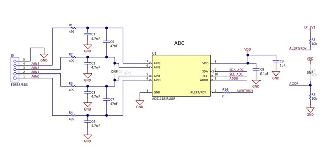
    Can the connections in the above diagram (copied from ADS1115EVM) be used directly if a single-ended measurement configuration is used?

    Do C5 and C7 need to be remove?

    Do the value of R1, R2, R3, R4 and C1, C2, C3, C4 need to be changed?

    Best regards,

    Will

  • Hi Will,

    If your input is 0 to 5V then you will need to make sure VDD is 5V.  You will also need to use the input range set to +/-6.144V in the configuration register.  C5 and C7 can be removed.  The remaining filter values are a good starting point.

    Best regards,

    Bob B

  • Ok, thank you.