This thread has been locked.

If you have a related question, please click the "Ask a related question" button in the top right corner. The newly created question will be automatically linked to this question.

DAC60508: Cannot Read Device ID or Any Other Registers; SDO is Seemingly Random

Part Number: DAC60508

Hello,

I am relatively new to setting up and debugging SPI communication, so I appreciate your patience in advance. 

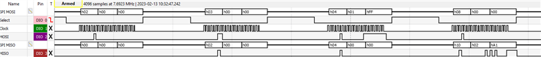
I've reflowed the DAC60508 to my board and tried to read the DEVICE ID unsuccessfully. I've verified the SPI mode to be correct, in mode 1, verified below. I checked the forums here and saw other comments recommending writing to the TRIGGER register to perform a soft reset, clearing the LDAC, writing to the SYNC register to clear BRDCAST enables, and clearing the CONFIG register to make sure FSDO is 0, despite that being the default value.

Subsequent SPI access cycles with the same MOSI bytes as above will return semi-stable but nonsensical values from the DAC, none of which are the DEVICE ID or even an echo of the first byte from the previous access cycle.

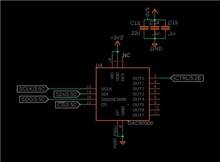
Here's the DAC schematic for my board:

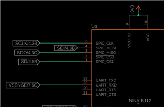
I am currently debugging with a nRF52840, no lines are pulled up on the SPI, but the DAC is the only interfaced SPI device. I don't believe this would be the issue, but again I'm a bit new to this so it could be!

Any help would be greatly appreciated!

  • We are reviewing now.

  • Hi Drew,

    Could you tell me what frequency your SPI clock is running at? On page 28 of the datasheet, table 7 shows the timing requirements for the SPI interface and in there you will see that read operations have a lower maximum clock speed than write operations.

    Thank you,

    Garrett Shirley

  • Hi Garrett,

    Thank you for your reply. I was running the SPI clock speed at 500kHz here. I tried frequencies up to 8MHz with the same result.

    Adding a bit more context above, after the set of 6 access cycles above, I repeat the 6 cycles again a second later. The first three cycles then have bits on the SDO line that aren't present in the first set. In subsequent loops of the 6 cycles, the SDO line stays the same as seen below.

    Here's one more example where I attempt to soft reset then read the DEVICE ID repeatedly:

  • Hi Drew,

    Approximately how long of a delay is there between your command to trigger a software reset and the following commands? In section 8.3.3.1 on page 24 of the datasheet it indicates there must be a 250us delay after a reset event before communication with the device is valid.

    Thank you,

    Garrett Shirley

  • Hi Garret,

    I did not catch that before; I had tried manually stepping through each access cycle before with at least a second in between each with no success. I've added a 300us delay now after the soft reset, here's the result:

  • Hi Drew,

    Could you confirm for me that you are using a DAC60508Z or DAC60508M and not a DAC60508ZC or DAC60508MC? Only the DAC60508Z and DAC60508M have a pin with SDO functionality. The package option addendum on page 44 of the datasheet shows what markings will be on your device depending on which specific version you have.

    Thank you,

    Garrett Shirley

  • Hi Garrent,

    The full MPN is DAC60508MRTER. So I believe that falls within the DAC60508M category.

    If it helps, here is a screenshot of DAC placement and the pin headers I am using to interface the DAC with the nRF52840-DK. The microcontroller below it is not soldered onto the board.

  • Hi Drew,

    Have you been able to observe any change on the DAC output despite the issue with reading back data? I would like to confirm that you are communicating with the device correctly. In your first post the SPI frame does appear to be in the correct mode, but seeing the DAC output change from the startup value would confirm.

    If you write:

    SYNC = 0x0000

    CONFIG = 0x0000

    GAIN = 0x01FF

    DAC0 = 0x0000

    You should see the output on DAC0 go to 0V. Can you confirm that?

    Thank you,

    Garrett Shirley

  • I can confirm that I see 0V on the DAC0 output after sending these write commands. If the next step would have been to check the output with a higher voltage set, I just tried DAC0=0x0FFF with the same result, 0V on the DAC0. 

    I've ordered a dev kit which I'm expecting to arrive this week in case it will help to debug the issue. It is for the 80604, but afaik they should be similar enough to help in this situation.

  • Hi Drew,

    Could you measure pin 1 of the DAC and confirm the reference voltage is ~2.5 V? Additionally, if possible could you upload the analog waveforms from one of your SPI commands? I suspect the issue is with the SPI command formatting. The DAC80604 EVM should be able to be used as a reference for communicating with your DAC60508 as they use the same SPI format and have similar overall operation. 

    Thank you,

    Garrett Shirley

  • Here is two consecutive loops of the write commands mentioned, with setting the DAC0 output to max.

    I've confirmed pin 1 voltage reference to measure ~2.5V.

    Repeated loops of writes the with setting the DAC0 to 0V results in this:

    That is reassuring to hear. I'll message here when it arrives.

  • Hi Drew,

    Looking at figure 65 on page 29 of the datasheet, I am seeing SCLK being high as CS transitions to low. On your scope captures, SCLK is low when CS transitions. Can you change your SPI settings so it is idle high while making sure data is still latched in on the falling SCLK edge? Additionally, looking at your latest scope captures, when you are writing to register 8 to set DAC0 to full scale, the register data is actually left justified. So, to set the DAC to full scale output, you would need to write 0xFFF0, not 0x0FFF. Your write of 0x0FFF to register 8 and given the settings for the reference divider and DAC gain, you should see an output of ~0.155 V based on equation 1 on page 21 of the datasheet.

    Thank you,

    Garrett Shirley