This thread has been locked.

If you have a related question, please click the "Ask a related question" button in the top right corner. The newly created question will be automatically linked to this question.

AFE4490SPO2EVM: AFE4490SPO2EVM in bypass mode

Part Number: AFE4490SPO2EVM
Other Parts Discussed in Thread: AFE4490,

Hi all,

I want to evaluate the AFE4490 for a new product application and I am going to buy the evaluation kit AFE4490SPO2EVM.

I need to use an AFE that can output analog signals so that I can sample with the internal ADC of my own MCU.

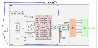
I noticed that I can use the BYPASS MODE, with analog output voltage that becomes available on two pins RX_OUTP and RX_OUTN.


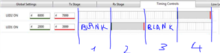
Now, I would like to use only one single led (IR one) and in a "continous" way, meaning without the 4 phases (as it is by default, see attached figure from datasheet).

I need that only the LED1 is ON for the 100% of the Pulse Repetition (that loses at all its meaning), so that, sampling on RX_OUTP and RX_OUTN, I can read at any times data from PD triggered by LED1 only.

Basically I don't want to have LED 1 ON, LED 2 ON, Ambient 1 and Ambient 2 periods, but only LED 1 ON for all the time of the PR (in this way the PRF becomes meaningless).

Is there a way to set this kind of configuration? I need to know that before completing the purchase.

Thanks for the help, looking forward to read your advices.

Regards,

Alessio


  • Hi,

    i will need another 24 hours to get back to you.

    Thanks.

  • Hi,

    Really apology for the delay.

    1. "I need to use an AFE that can output analog signals so that I can sample with the internal ADC of my own MCU."

    Our AFE always outputs digitized ADC code, so directly interface or sample with the analog signal inside the AFE is not recommended -
    Page 47 of datasheet

    "

    8.4.2 AFE Analog Output Mode (ADC Bypass Mode) This mode is only intended for use in system debug. Note that this function is not recommended for production use because of the minimal device production testing performed on this function.

    The ADC bypass mode brings out the analog output voltage of the receiver front-end on two pins (RXOUTP, RXOUTN), around a common-mode voltage of approximately 0.9 V. In this mode, the internal ADC of the AFE4490 is disabled. Figure 73 shows a block diagram of this mode.

    "

    2. Would you please clarify a bit more on ""continous" way" and "LED1 is ON for the 100% of the Pulse Repetition (that loses at all its meaning),"

    Do you mean you want one LED constantly ON without pulsing nor OFF ?

    The AFE doesn't support that. However, may I ask what might be the intention or purposes?

    Thanks.

  • Hi, thanks for your reply.
    I need to test my acquisition platform (with a built-in ADC) for PPG measurement purposes.
    I need a performing AFE that can output an analog PPG signal that my platform can sample (for debugging purposes).

    I would like LED1 (IR) to be constantly on without pulsing or turning off, this is because I manage the sampling times in my platform and I don't want to take the risk of asking the AFE for a sample and having LED1 off at that time. I cannot use ADC_RDY to be synchronized with the AFE because my ADC has to sample at the right time when the MCU tells it to sample, I cannot wait the ADC_RDY interrupt (this is a project spec).

    All I need is an analog PPG signal that is output continuously (perhaps taking advantage of an IR led). If you have any advice (or other products I can use) to achieve this it would be greatly appreciated.

    Regards,
    Alessio

  • Hi,

    Just curious, if you want an LED constantly ON and also not using the AFE IC's ADC and using your own ADC.

    Then, why do you need the AFE IC?

    Can't you just use any simple current source or voltage+resistor to turn ON the LED?

    Thanks

  • Hi,

    basically I am interested in exploiting the blue-circled part of your product (ideally the TX part is just a single LED without any control block)

    I can design my own PCB with those components but it would be really faster if I could use directly the AFE4490SPO2EVM.

    It is just a matter of time and it would take me a long time to design and have my own custom pcb fabricated.

    Thanks,

    Alessio

  • Hi,

    Let me know if i understand correct,

    all you want is the function in the blue circle before the ADC? correct?

    We may not support that kind of manner or usage.

    My suggestion might be you could start with building the TIA, amplifiers and active filters using discrete components and bread boards first and use Oscope to sample&read the signal. And once you prove the concept and verified it all works, then you may start doing some PCBA works and reverify&revalidate again.

    Then, after that you may make decision whether you want to shrink further the size further or with other additional feature, then considering buying one of TI"s biosensing EVMs for evaluation and reiterate the experiments&tests&V&V data collection&analysis processes.

    Thanks

  • all you want is the function in the blue circle before the ADC? correct?

    Correct.

    My suggestion might be you could start with building the TIA, amplifiers and active filters using discrete components and bread boards first and use Oscope to sample&read the signal. And once you prove the concept and verified it all works, then you may start doing some PCBA works and reverify&revalidate again.


    Yeah, that should be the point. The only problem is that I need the sensing node ready to be used in a really short time (something like 1 month). I am pretty sure I am not able to build a working electronics in such a short time (considering the design, the components selection/delivery, the V&V tasks). This is why I am looking for something off-the-shelf to use.

    Do you have anything that can be used in my situation? Also something that is far simpler than AFE4490SPO2EVM is ok, I selected the AFE4490SPO2EVM only because I read about the bypass mode in the datasheet.

    As last option, I can try to exploit the AFE4490SPO2EVM in bypass mode but with only 1 led (IR) on. In this case I have an alternation only between LED1 sampling and ambient sampling, am I right? I can try to implement a kind of synchronization, but I need to be able to switch off LED2 (red one), is it possible?

    Thanks,

    Alessio

  • Hi,

    You may purchase an EVM to start doing some tests and evaluations to see whether it meet your need.

    Thanks

  • Hi,

    yes that was my idea.

    If it is possible to switch off LED2 on the AFE4490SPO2EVM (need your confirmation, in the timing control window there should be no more "Sample LED2" and "Sample ambient LED2") I am going to select this one exploiting the bypass mode.

    Thanks,

    Alessio

  • You could simply either not install the 2nd LED or set the LED current to 0.

    Datasheet page 76 

    and

    Figure 116

    Table 6

    Thanks

  • Ok nice, thanks for the references.

    Setting LED current = 0, I have not clear if it means that "LED2" and "LED2 Ambient" are not part of the timing control schema anymore (so I have only 2 slots instead of 4 each cycle) or if there are allocated timing slots (so each cycle is made of 4 slots anyway) but LED2 is just OFF.

    Thanks for the clarification.

  • Hi,

    sorry if I was not enough clear but mine was a question.

    Setting LED current = 0, I still have the doubt between the following two options and I'd like to have a clarification:

    1) "LED2" and "LED2 Ambient" are not part of the timing control schema (so I have only 2 slots instead of 4 each cycle)

    2) "LED2" and "LED2 Ambient" have allocated timing slots (so each cycle is made of 4 slots anyway) but LED2 is just OFF

    I need to know which option is the right one, 1) or 2).

    Thanks,

  • Hi,

    Sorry, I don't quite understand your questions? Could you please clarify what are you asking?

    Thanks

  • Sure.

    Here in the timing control schema, we have 4 different timeslots (1 for LED1 ON, 1 for LED2 ON, 2 blank for the ambient sampling).

    If I set LED2 current = 0, should I have a schema made of only 2 timeslots alternating (1 for LED1 ON, 1 blank for ambient sampling)?

    Or maybe do I always have a schema made of 4 timeslots, just during LED2 ON phase the led is switched off?

    If I want to be synchronized with ADC_RDY, I need to know if each Pulse Repetition Frame is made of 4 or 2 timeslots (because my need is to sample only during LED1 ON, so I need to know if I have to sample once every two or every four times).

    Thanks,

  • Hi,

    Sorry, after some consideration, we may not support what you are trying to do as it's not a normal usage/operation for this AFE4490.

    Thanks