This thread has been locked.

If you have a related question, please click the "Ask a related question" button in the top right corner. The newly created question will be automatically linked to this question.

ADS1298: General questions about ADS1298 design

Part Number: ADS1298
Other Parts Discussed in Thread: OPA170, ADS1299

Hi all, 

First off, thanks for the support - I have found this forum to be very helpful when I have general questions about TI products.   I am designing for a wireless EEG application, and am looking at using the ADS1298 (or 1296) as my converter.   I had a few questions about signal conditioning on the front end of the system:

 - The head electrodes will mate almost directly with a PCB, which will have about 3-4" of trace length/routing to get to the ADS1298.   I was wondering if there would be any benefit to adding a buffer interfacing at the electrode/PCB mating point to drive the short trace run prior to hitting the input stage of the 1298? T he general idea was to use something like an OPA170 at the electrode attach with a low impedance output driving the IN-P stage for each channel.  I know the data sheet for the 1299 suggests there is no need for any intermediary circuitry, but I wasn't sure if the same general design approach can be used for the 1298.   

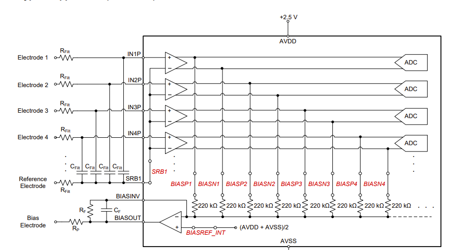
 - We are planning on using a single-ended approach, with a common reference electrode connected to all of the IN-N inputs.   I am going on a design note in the 1299 datasheet for "referential montage" (shown below) connected to SRB In our case, we would just be connecting to IN-N of each channel, but including the differential capacitor for anti-aliasing, whilst keeping CMRR in a decent place.   Does this also make sense for the 1298?   

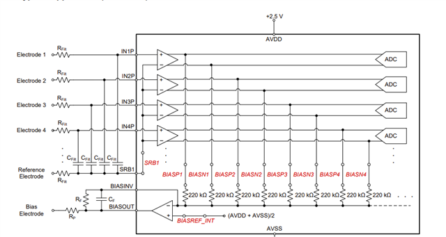
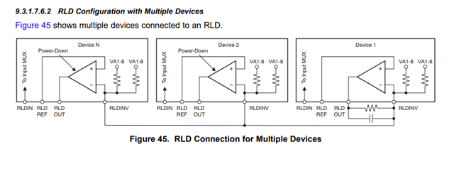
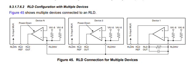
 - This application will use two 1298's - One one each side of the head (around the temple area).   I noticed that there is an short mention of multiple devices with one RLD, and was wondering if I need to pay attention to this.   Currently, the plan was to use the internal RLD closed loop feeding the bias electrode on one side of the head, and have the common reference electrode on the opposite side temple.   The idea is that we can set the common mode with one ADS1298, and use the reference on the other 1298 to feed both chips.   Is there an error in this approach, and should I think about doing this differently?   How would the below image be used with multiple 1298's (what is the application?)


  • Hi,

    1. Could you please clarify a bit more "adding a buffer interfacing at the electrode/PCB mating point to drive the short trace run prior to hitting the input stage of the 1298?"

    e.g. where and how?   Some customers may or may not add buffer, but they will still need to do tests&V&V before making/moving to final decision; especially, if they are using lead detection, that buffer may affect. So, please do some experiments&tests&data collection&analysis&V&V.

    2. "single-ended approach, with a common reference electrode connected to all of the IN-N inputs."

    Not quite sure what you meant?  Are you using ADS1298 or ADS1299?   For ECG or EEG application? Would you please clarify?

    ADS1298 is used for ECG application and it has to be in differential inputs as that is how ECG signals are formed and measured.

    ADS1299 is designed for EEG application, and there could be referential or sequential montage.

    So, I am not sure which IC and applications are you referring to?

    3. Ok, now I see you are thinking of using two ADS1298s. Do you want to daisy chain them or not?

    Some customer use more ADS1298 for more ECG leads.

    Yes, customers can start with 9.3.1.7.6.2 RLD Configuration with Multiple Devices, but in the end, customers will still need to do experiments&tests&data collection&analysis&V&V before making decisions.

    It's suggested to get an ADS1298EVM to start evaluatte and test.

    Thanks,

  • I am referring to the ADS1298.  The question calls out the 1298 and EEG for the application.   I am asking if the 1299 datasheet applications notes can apply to the 1298.  ADS1298 is also (in the datasheet) used for EEG, so I am confused as to why you say only the 1299 can be used for EEG.   

    Are you saying that the 1298 can't be used for single ended by feeding a reference to AVSS?   

  • Hi,

    Depending on the EEG signals customers are interested.

    However, ADS1299 is more suitable for EEG applications.

    May I ask are you interested in EEG or ECG applications?

    And, when you say single ended? are your referring to power supply?

    ADS1298 can take both Unipolar or Bipolar Supplies per ADS1298 datasheet page 97

    Thanks

  • Let me be more specific - The application is EEG, NOT ECG.

     - By single ended-I meant unipolar supply, so hope that clarifies.   My design approach was to use a common reference electrode into the IN-N (as mentioned above), and the electrodes would feed the IN-P inputs.

    - I can't purchase the 1299 or any version of it because they are not available from TI right now.   Also, the cost of the 1298 is less.   Because of that, I want to consider using the 1298 for EEG, but I wanted to see if the 1299 datasheet applications can apply.   So, again, I am interested in EEG for the 1298.

     - Before I spend $200 on the PDK, I wanted to get some basic answers to my questions as mentioned above.   So, back to the original questions:

    a.   Why can't the referential montage work for the 1298 (tying refence to IN-N with differential capacitors)?   Instead of going to SRB, why can't you do the same thing by making the reference common to the IN-N?   I would like to understand why this won't work (without buying the PDK first).   

    b.   What is the actual application for multiple RLD connections?   How is this used, and why?  

    c.  Why is the 1299 better than the 1298 outside of noise floor, SRB, and advanced routing options?   Can the 1298 not be used for regular EEG?   What do you mean by "Depending on the EEG signals customers are interested."?

  • Any thoughts on this?  If ADS1298 is not good for EEG, or if there is some front end circuitry needed to make it usable, please let me know.  I have an available buffer in place, which could be a gain stage if needed to get above converter noise,  

  • Hi,

    I will try to get back to you by 3/3.

    Thanks

  • Is there someone else that can help with this between now and 3/3?    Presumably, there are additional apps engineers to weigh in on this.   

  • We will try to get back to you, thanks for your patience.

  • This is not helpful, I need answers before 3/3.   I am trying to work TI's chip into a design, but I need support ASAP.   Please add in another engineer to take my questions while you are busy.   Thank you.

  • Hi,

    For "Let me be more specific - The application is EEG, NOT ECG.",

    Then, it's suggested to use ADS1299.

    ------------------------------------------------------------------------

    For "use a common reference electrode into the IN-N (as mentioned above), and the electrodes would feed the IN-P inputs."

    Do you mean 

    Figure 72. Example Schematic Using the ADS1299 in an EEG Data Acquisition Application, Sequential Montage

    or

    Figure 73. Example Schematic Using the ADS1299 in an EEG Data Acquisition Application, Referential Montage

    or 

    none of above?

    --------------------------------------------------------------------------------------------------------------------

    For " I can't purchase the 1299 or any version of it because they are not available from TI right now"

    I will discuss this with other internal team member and get back to you.

    --------------------------------------------------------------------------------------------------------------------------

    For "wanted to see if the 1299 datasheet applications can apply.   So, again, I am interested in EEG for the 1298.

    Okay, thanks for making this clear.  Using ADS1298 for EEG application.

    No, you may not apply 100% from ADS1299 to ADS1298.

    ---------------------------------------------------------------------------------------------------------------

    For "Why can't the referential montage work for the 1298"

    Customer will need to use an EVM to evaluate whether applying referential montage on ADS1298 for EEG application meet their needs/applications as even for EEG applications different customers have different interest needs and frequency band region.

    -------------------------------------------------------------------------------------------------------------------------

    For "What is the actual application for multiple RLD connections?   How is this used, and why?  "

    Not sure about what you mean be "multiple" ?

    The purpose for RLD is designed for ECG application to drive a known voltage to human body to avoid human body floating in an unknown potential, which could be outside the chip's acceptable/working range.

    -------------------------------------------------------------------------------------------

    Why is the 1299 better than the 1298 outside of noise floor, SRB, and advanced routing options?   Can the 1298 not be used for regular EEG?

    ADS1299-

    Input-Referred Noise: 1 μVPP (70-Hz BW)

    • Programmable Gain: 1, 2, 4, 6, 8, 12, or 24

    And it was mainly designed for EEG application.

    ADS1298-

    Input-Referred Noise: 4 μVPP

    Programmable Gain: 1, 2, 3, 4, 6, 8, or 12

    And it was mainly designed for ECG application although some people may use it for EEG.

    ----------------------------------------------------------------

    "Depending on the EEG signals customers are interested."

    Different customers and researchers have their own particular interest EEG signal band as well as the detail of the small amplitude(i.e. related to the gain setting) they wan to acquire/observe.

    One example might be, if you look at ADS1299 datasheet page 67 10.2.1 Design Requirements

    Bandwidth 1 Hz - 50 Hz Minimum signal bandwidth 10 μVPk

    ADS1299(EEG oriented) is capable to acquire 10 μVPk whereas ADS1298(ECG oriented usually just need mV range) 

    And, ECG signal usually doesn't need DC component -

    And, there could be other reasons from customer's sides that they choose ADS1299 over ADS1298 as we are not EEG signal experts.

    ------------------

    Thanks

  • To answer your questions in order:

     - Figure 73 describes my application as mentioned above.

     - Regarding multiple RLD.   From my original question  Datasheet for 1298:

     - I would suggest that TI change the verbiage for the 1298 to remove EEG from the literature if it is not properly supported with applications info. 

  • User can try to configure ADS1298EVM in Referential Montage and see whether it meets the EEG applications.
    Connect/cascade Multiple RLD together is needed if one is using multiple ADS1298 for more ECG leads application.

    Thanks

  • Perhaps TI can provide application circuits for EEG using the 1298 for customers that are interested in using the chip for EEG-only.   There is a lot of application information for the 1299 as it relates to EEG, but none for the 1298, even though it is in the datasheet.   I think this is confusing for developers who are trying to use the 1298 series to save cost and because they are still available.

  • Thanks. We don't have that at this moment.

    -----------------------------------------------------------------------------------

    User can try to configure ADS1298EVM in Referential Montage and see whether it meets the EEG applications.

    -------------------

    I am still waiting for the lead time and supply info for the ADS1299.

    Thanks

  • So, is the plan to develop application info for 1298 series and EEG?   It would sell a lot more product for TI, especially because of low availability for 1299.   When can we expect for apps info for 1298?   

  • There is no definite timeline yet.

    User can try to configure ADS1298EVM in Referential Montage and see whether it meets the EEG applications.

  • Thank you reaching out. 

    ADS1299 Lead times change regularly and vary with quality.

    Please check with your local distributor or contact the TI Customer Service Center for further assistance. 

    And, I will reach out to you via email.

  • What do you mean by "vary with quality"?

  • Sending you email now.

    Thanks.