This thread has been locked.

If you have a related question, please click the "Ask a related question" button in the top right corner. The newly created question will be automatically linked to this question.

ADS1293: Battery Monitoring Problem

Part Number: ADS1293


Hello,
I use custom ads1293 board and I have faced a problem. I use lipo battery for the board. I need to calculate battery level and wanted to use feature of the ads1293.

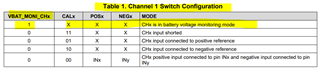
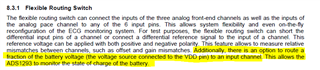
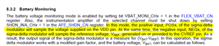
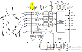
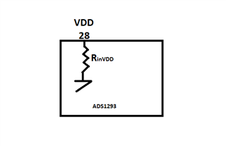
The battery voltage source is connected to the VDD pin. Hardware designed referanced from the datasheet and it works properly. Problem is I can not read ADC value of the battery over FLEX_CH_CN1. I set "VBAT_MONI_CN" register as 0x01 and also set "AFE_SHDN_CN" register as 0x01 too. 

According to datasheet of the ads1293 POSx of the FLEX_CH_CN1 register need to be read ADC value of the battery but I always read  FLEX_CH_CN1 as 0x00 or last written value. VBAT_MONI_CN and AFE_SHDN_CN resigters were writen and read successfully.

Also when I read ERROR registers value of ERROR_RANGE1 is 0x14 which is "channel 1 instrumentation amplifier negative output near negatice rail" and "channel 1 instrumentation amplifier negatice output near positive rail". Do you thin the error code related the battery monitoring?

Could you kindly please tell me which reason can cause the problem?

Yours Truly,
Ali Serbetci

  • Hi,

    I will try to get back to you by 3/3.

    Thanks

  • Hi,

    Do you have an ADS1293 evaluation kit/board EVM?  It's suggested to test the feature you want using the EVM.

    -----------------------------------------------------------------------------------------

    What does it mean by "calculate battery level"?

    What is the battery voltage? How does it connect/relate to the VDD pin?

    And, how do you connect/supply the battery to ADS1293?

    -----------------------------------------------

    There is no "VBAT_MONI_CN" register, are you referring to "VBAT_MONI_CH"?

    There is no "FLEX_CH_CN1" register, are you referring to "FLEX_CH1_CN"?

    FLEX_CH1_CN = 0x00 means no test signal, and Positive and Negative inputs terminals are disconnected.

    -------------------------------

    ADS1293 datasheet page 14

    "If the battery voltage monitoring mode is enabled by programming the VBAT_MONI_CHx bit in the FLEX_VBAT_CN register, then the POSx and NEGx bits programmed in the FLEX_CHx_CN register no longer have any effect. The battery voltage monitoring mode thus takes priority; this is shown in the first row of Table 1."

    And page 15

    "

    8.3.2 Battery Monitoring

    The battery voltage monitoring mode is enabled by setting bit VBAT_MONI_CHx = 1 in the FLEX_VBAT_CN register.

    Also, the instrumentation amplifier of the selected channel must be shut down by setting SHDN_INA_CHx = 1 in the AFE_SHDN_CN register.

    In this mode, the positive input, POSx, of the sigma-delta modulator will sample the voltage supplied on the VDD pin.

    At the same time,

    the negative input, NEGx, of the sigma-delta modulator will sample the reference voltage, VREF, generated on or provided to the CVREF pin.

    As a result, the output signal of the sigma-delta modulator is a measure for (VBAT-VREF). In this operation, the sigmadelta modulator works with a modified gain factor, and the battery voltage, VBAT, can be calculated as follows equation (1)

    The value of ADCMAX is dependent on the configuration of the digital filters, and the corresponding ADCMAX values are listed in Table 8 through Table 11.

    The battery monitoring mode is targeted for battery operated systems within a voltage range of 2.4 V to 4.8 V.

    The battery monitoring mode cannot be used when the ADS1293 is powered from a regulated 5-V supply because it risks saturating the sigma-delta modulator

    "

    What is the battery voltage? How does it connect/relate to the VDD pin?

    What might be your VDD and Vref and CVREF? Is your Vref=2.4V?

    -------------------------------------------

    Thanks

  • Hi Yang,

    I do not use ADS1293 evaluation kit/board EVM. I use custom board designed by getting referanced of ads1293 datasheet.

    "calculate battery level" means that voltage value of the lipo battery which is power supply of the custom board.

    The board is supplied by lipo battery and on the board there is high quality voltage regulator chip which is fixed for 3.3V.

    VDD pin of Ads1293 is connected directly from lipo battery supply which works between 4.2V-3.7V. Supply voltage of Ads1293 is 3.3V which comes from regulator.

    The bits are VBAT_MONI_CHx = 1 and SHDN_INA_CHx=1 set and confirmet by reading their registers. The problem is after setting these bit there is no changing on FLEX_CHx_CN register. I can not read on POsx and NEGx values the resi . It is always 0x00 or the ex-value which set before.

    The Vref is 2.4V.

    I have already shared error range of the channel which I set for battery monitoring.

    The hardware is working properly, reading and writng registers of Ads1293 has no problem, problem is  as I wrote just  before I can not read POSx and NEGx values on FLEX_CH_CNx  register.

    Thank you!

  • "VDD pin of Ads1293 is connected directly from lipo battery supply which works between 4.2V-3.7V."

    Any current limiting resistor or fuse? Did you verify the current is not too low or too large?

    on the evm, it uses a LDO LP2985AIM5-3.3/NOPB that can provide upto 150mA.

    ---------------------------------------------------

    ADS1293 datasheet

    "If the battery voltage monitoring mode is enabled by programming the VBAT_MONI_CHx bit in the FLEX_VBAT_CN register, then the POSx and NEGx bits programmed in the FLEX_CHx_CN register no longer have any effect. The battery voltage monitoring mode thus takes priority; this is shown in the first row of Table 1. F"

    once VBAT_MONI_CHx is set to 1, the corresponding channel's CALx, POSx and NEGx are don't care.

    --------------------------------------------------------

    Do you have an ADS1293 evaluation kit/board EVM?  It's suggested to test and compare the feature you want using the EVM.

    thanks

  • Hi Yang,

    VDD pin directly connected to lipo battery source which works between 4.2V-3.7V.

    I did not verify current of the VDD pin. Do you mean there is current operating range for the VDD pin? On the datasheet I just have the information that:


    Inform me please if there another information about the VDD pin.

    "once VBAT_MONI_CHx is set to 1, the corresponding channel's CALx, POSx and NEGx are don't care." I know that POSx and NEGx has no effect after set the VBAT_MONI_CHx pin as 1 but I expect the read on them ADC value of voltage source and referance voltage according to datasheet.


    The problem is these bits(POSx and NEGx) of the  FLEX_CHx_CN is "0"  or last written value and always stable when I set registers for battery monitoring.

    I do not have ADS1293 evaluation kit/board EVM.

    Thank you.

  • Any current limiting resistor or fuse? Did you verify the current is not too low or too large?

    Input current at Any Pin

    Please check the current consumption.

    ---------------------

    It's suggested to test and compare the feature you want using the EVM.

    Thanks

  • Hi Yang,
    VDD pin directly connected to source without fuse or resistor. Do you think this is the reason of the problem?  Is it posible to know from any error registers of ADS1293 if there is current problem of the input pin? Design is referanced by datasheet below:


    So on the pin there is no fuse or resistor. 


    Thank you for the information and kindly answer my last questions. 

    Yours Truly,
    Ali Serbetci

  • That is a conceptual block diagram, not a real implementation schematic, i.e. it doesn't contain&represent all the required peripheral components.

    Designers&developers should take care of the protection of the product.

    Thanks

  • Hello Yang,

    I have been analyzing ADS1293EVM.pdf to understand how battery voltage monitoring work on the development board. Could you please enlighten me aboout my question?

    On the ADS1293EVM schematic battery input is connected to IC called LP2985AIM5-3.3/NOPB and the IC has fixed voltage out. My question is how can I measure changing voltage of the battery if the output is always fixed?


    So if "BATT_LDO_OUT"   is fixed VDD is fixed too thus decrasing battery boltage level will not be monitoring on POSx of the FLEX_CHx_CN register.
    We really want to use the feature of the ADS1293 and please support us to find best option for our design.

    Thank you.

  • Hi,

    The voltage from  LP2985AIM5-3.3/NOPB won't be fixed if the battery starts dying out.

    ---------------------------------------------------------------

    There are always some LDO or regulator between battery and IC e.g. TPS61220DCK or LP2985AIM5-3.3/NOPB
    and fuse or ferrite bead e.g. BLM15HG102SN1D.

    And, the EVM can serve a purpose for user to evaluate if they want to depopulate the LP2985AIM5-3.3/NOPB and connect the battery directly with some current limiting resistor/fuse/ferrite bead in the way.

    It's suggested to test and compare the feature you want using the EVM.

    ----------------------------------------------------------------------------

    Any current limiting resistor or fuse? Did you verify the current is not too low or too large?

    It's suggested to test and compare the feature you want using the EVM.

    ---------------------------------------------------------------------------

    Designers&developers should take care of the protection of the product.

    Thanks

  • Hi Yang,

    I have one more question. Is it known inside resistance of the VDD pin? I have checked datasheet and could not find such a information. I hope the picture explain what kind of information I need exactly.

    Yours Truly,
    Ali Serbetçi


  • Hi,

    I will need to discuss this with internal team to see whether we have/can disclose this info before getting back to you.

    Thanks

  • Hi,

    we don't have ADS1293's VDD internal resistance info to disclose.