This thread has been locked.

If you have a related question, please click the "Ask a related question" button in the top right corner. The newly created question will be automatically linked to this question.

ADS1299: data corrupted / spikes when adding delay before reading

Part Number: ADS1299

Hello, 

I have a really strange problem with my custom board (ADS1299 + Atmel SAMD21G18A): sometimes ADS1299 gives corrupted data, either from one channel, or from several channels.

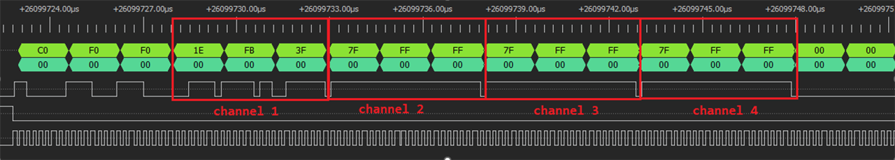
My ADS1299 is working in single-shot mode, with internal 2.048MHz clock. The microcontroller sends START command at a frequency of 2000Hz, it waits for ADS1299 DRDY interrupt, then reads ADS1299 buffer. The ADS1299 sends data to the microcontroller via SPI (SPI baud rate 4M, ADS1299 SPS = 16k).  ADS1299 channel 1 - channel 4 for EEG data acquisition, channel 5 - channel 8 off. 

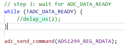
I should mention that there is a small delay (~3us) in my code between ADS1299 DRDY and the start of microcontroller reading. 

Below shows one example. As no electrodes are connected, I am supposed to get 7FFFFFh all the time. However, as you can see from the screenshot, some data got corrupted. 

I connected a logic analyzer to the ADS1299 SPI pins, and this confirms the corruption of data before they are sent to the SPI line. Below shows an example (here channel1 data is corrupted):

The strange thing is, when I delete my delay (meaning that the microcontroller waits infinitely DRDY signal and launches read operation as soon as ADS1299 data is ready), this bug seems disappeared and I got stable data. 

I tested with ADS1299 internal test signals (square waves), I changed SPI speed, same problem. 

I found a similar post here: https://openbci.com/forum/index.php?p=/discussion/423/ads1299-with-arduino-due-sampling-problem

Could someone explain what I am doing wrong? 

Thank you very much.

Kind regards 

Xin

  • Hi,

    I will try to get back to you by 3/3.

    Thanks

  • Hi,

    Do you happen to have an ADS1299 evaluation kit/board(EVM)?

    Since you have a logic analyzer, you can probe the signals on both the EVM and your board and do a side by side comparison.

    -----------------------------------------

    For "The microcontroller sends START command at a frequency of 2000Hz"

    what do you mean by this?  Does the MCU send 2000 times START command per second?

    Why do you want to sending START command 2000 times per second and do you use STOP command?

    "When the START command is sent to the device, keep the START pin low until the STOP command is issued."

    Pleas take a look of 9.4.1.1 Settling Time and Figure 40. Settling Time

    "Note that when START is held high and there is a step change in the input signal, 3 × tDR is required for the filter to settle to the new value. Settled data are available on the fourth DRDY pulse."

    tDR denotes the output data time period

    What is the output data rate DR[2:0] setting?

    Do you send the RDATA command?

    How frequent do you see the /DRDY you observe?  

    Please take a look of ADS1299 datasheet 9.5.3.9 RDATA: Read Data and  Figure 47. RDATA Usage.

    And make sure the SCLK rate complies with ADS1299 page 39 - "For the RDATA command, the limitation applies if data must be read in between two consecutive DRDY signals."

    and page 40

    "System commands and the RDATA command are decoded by the device on the seventh SCLK falling edge."

    "Be sure to follow SPI timing requirements when pulling CS high after issuing a command."

    --------------------------------------------

    For "a small delay (~3us) in my code between ADS1299 DRDY and the start of microcontroller reading", 

    what do you mean by "the start of microcontroller reading"? any signal edge or command to represent this?

    Does that delay still meet the timing requirement for ADS1299

    e.g. ADS1299 datasheet 9.4.4.1 Data Ready (DRDY) and Figure 41. DRDY with Data Retrieval (CS = 0)

    ----------------------------------------

    Regarding to your OpenBCI post -

    The original post replied - "Thank you for commenting. I was able to fix the problem.. It was due to a small delay in reading data from the chip."

    So, you may need to double check in the MCU code/side as well.

    ---------------------------------------------

    FYI, ADS1299 is an 8 Channel device, so it will always output 8 channels of data.

    Thanks

  • Dear Chien-Chun,

    Thank you very much for the detailed reply, and sorry for the late reply. 

    I unfortunately don't have an EVM, I'll try to get one for further development. 

    For my custom board, START pin is grounded, so it is always LOW. 

    The microcontroller sends a START command, waits for DRDY falling edge to come, then sends RDATA command, then reads 27 Bytes data from ADS1299 buffer. This whole process is repeated at a frequency of 2000Hz. 

    As ADS1299 is working in single shot mode, I do not use STOP command. 

    The data rate [DR2:0] in my code is 000 -> 16kSPS. 

    The delay (~3us) is located between the arrival of DRDY falling edge and sending of RDATA command. 

    Hope this is clearer now.

    The question was: when I deleted this delay (meaning that the microcontroller reads ADS1299 buffer AS SOON AS a DRDY falling edge triggers, the spikes (data corruption) seem disappeared and I got stable data.

    The openbci post says "due to a small delay in reading data from the chip", whereas my problem can be rather described as "due to a small delay BEFORE reading data from the chip", if this could be clearer. 

    Of course, I am not sure if my problem is indeed due to this delay, perhaps I did something wrong concerning SPI timing or something else. If you could give me some advice or inspiration, it would be really helpful. 

    Kind regards

    Xin

  • Hi,

    For 

    "when I deleted this delay (meaning that the microcontroller reads ADS1299 buffer AS SOON AS a DRDY falling edge triggers, the spikes (data corruption) seem disappeared and I got stable data."

    If you want to dig into further detail, then need to probe and compare signals waveforms when there is and no delay and than, and from both, comparing with the timing requirement for ADS1299

    e.g. ADS1299 datasheet 9.4.4.1 Data Ready (DRDY) and Figure 41. DRDY with Data Retrieval (CS = 0) and Figure 47. RDATA Usage

    Datasheet page 42 9.5.3.9 RDATA: Read Data

    "To retrieve data from the device after the RDATA command is issued, make sure either the START pin is high or the START command is issued."

    So, how did you connect the START pin?

    Do you think you can identify/locate/pointout  where that delay occur in the Figure 47. RDATA Usage?

    ----------------------------------

    Yes, it's suggested to get an EVM for signal waveform reference and comparioson.

    Thanks