- Ask a related questionWhat is a related question?A related question is a question created from another question. When the related question is created, it will be automatically linked to the original question.
This thread has been locked.
If you have a related question, please click the "Ask a related question" button in the top right corner. The newly created question will be automatically linked to this question.
My analog input signal is a positive voltage from a single-ended source. How should I configure the AMC1203 to accept this input, rather than a balanced input?
Hi Brian,
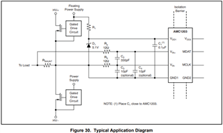
The typical application diagram in the datasheet provides and example schematic:
Connect the device ground and negative input to the ground/reference of your signal source.

We have several newer devices that may be better suited to your application and provide higher performance. What type of application are you working on?
Thanks, Alexander, that's the simple answer I hoped for. I didn't guess, from the diagram, that the answer would be so simple. I want to replace a conventional PWM circuit with this highly-oversampled implementation; I don't intend to drive a digital filter, like the AMC1210. I will evaluate my application with the AMC1203EVM.
By "newer," do you refer to the higher-frequency parts in the family, or to something else?
Hi Brian,
Happy to help.
The output is not a PWM but a digital bitstream proportional to the input voltage - requiring connection to an SDFM.
We have devices that operate up to higher clock frequencies, higher isolation ratings and higher accuracy.
Take a look at the AMC1303M2520 for example: https://www.ti.com/product/AMC1303M2520
Followup question, Alexander: am I right in thinking that I can bias the (-) input to VDD/2 to get low duty factor with near zero volts on the (+) input and high duty factor with near VDD on the (+) input?
Hi Brian,
Yes, you are correct. This scenario would result in the output clipping negative and positive.