Because of the holidays, TI E2E™ design support forum responses will be delayed from Dec. 25 through Jan. 2. Thank you for your patience.

This thread has been locked.

If you have a related question, please click the "Ask a related question" button in the top right corner. The newly created question will be automatically linked to this question.

ADS1220: ADS1220 measurement accuracy

Part Number: ADS1220

Hi team,

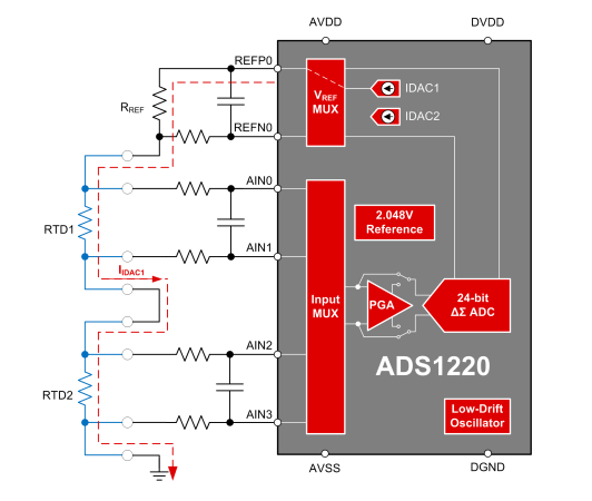
The customer wanted to make sure if the voltage across RTD1 equals to voltage across AIN0 and AIN1 or the voltage across RTD2 equals to voltage across AIN2 and AIN3. Actually there is the pcb parasitic resistor between RTD and ADS1220 AIN. When IDAC current flows from REFP0, REFN0, the customer are not sure whether the current would flows to AIN0. If there is current flows to AIN, there will be voltage drop between the voltage across RTD1 and voltage across AIN0 and AIN1. What is the voltage drop? Will the voltage drop influence the measurement accuracy?
  • Hale,

    For the configuration shown, the current will flow according to the red line.  Current will flow from IDAC1 through RREF, RTD1, and RTD2.  This current will not flow into AIN0, AIN1, AIN2, and AIN3.  These inputs are high impedance.  Thus, any filter resistors between the RTD and the analog inputs will not have any significant voltage drop or error.  There will be some very small input current that will flow (see figures 15 to 20).  This input current is typically in the nano-amps.  For input resistances less than 1k ohms the error voltage on the series resistors should be very small, but you may want to look at figures 15 to 20 and consider the temperature you are operating at to confirm if this error is significant in your application.  A Basic Guide to RTD Measurements is an excellent document that covers the details on how these circuits work.   You should recommend that your customer reviews this document as there are many things to consider to assure low errors and proper operation.

    I hope this helps.

    Best regards, Art

  • Hi Art,

    As you said, this input current is typically in the nano-amps. The customer need to evaluate accuracy, so how much nano-amps is the input current? About 1~10nA or 10~100nA or several hundred nA?

  • Hi Hale,

    Art has changed responsibilities within TI so I will attempt to answer.  You have asked about the input current and Art gave the answer in his last post.  Please review the ADS1220 figures 15 through 20 in the datasheet on page 12.  These graphs show what can be expected based on input voltage and operating temperature.  Current will increase with higher temperatures.  Notice that in the graphs that AIN3 is significantly larger than the other inputs due to leakage through the low-side switch connected to AIN3.

    Best regards,

    Bob B