This thread has been locked.

If you have a related question, please click the "Ask a related question" button in the top right corner. The newly created question will be automatically linked to this question.

ADS8519: ADS8519 +/-10V Input setup

Part Number: ADS8519
Other Parts Discussed in Thread: ADS8509

Hello,

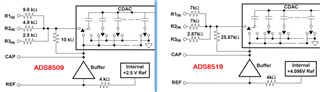
I am considering jumping from ADS8509 to ADS8519 ADC. I would like to avoid as many changes as possible to the surrounding circuitry (including the ADS8509 +/-10V input range connections). When computing how the voltage is divided internally given the old ADS8509 external setup, I get close to the same ratio. Do you foresee any issues with this? I am attaching the ADS8509 bipolar 10 input range set up and internal circuitry of ADS8519 for reference.

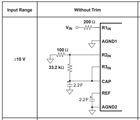
 *+/- 10V ADS8509 Connections. I would keep all external connections the same but instead use ADS8519.

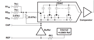
 *ADS8519 Internal Setup. (I believe the 25.67K resistor should be connected to ground btw)

  • Hi Jewel,

    I'm not sure that I follow what it is you mean by "(including the ADS8509 +/-10V input range connections)" above.  Do you mean keeping the external resistors in place?  This is the main difference between the two parts:

    The ADS8519 has 2x the reference voltage and different resistor values for RxIN.  If you go by Figure 30 in both the ADS8509 and ADS8519 datasheets, you can replace the 200 ohm resistor on R1in with 0 ohm, the 100 ohm from R2in to GND with 0 ohm, and leave the 33.2k ohm from R2in to R3in/CAP as 'DNP'.  That way the same PCB can accommodate either device with a simple 3 resistor BOM change.

  • Yes, I mean keep the same external resistors used on 8509 set up. Correct me if I’m wrong but when doing so, I get around 4.03 Volts at the divider for a 10 V input. The ideal situation would allow me to keep those external resistors so I can interchange between parts without even a 3 resistor change.

  • You can certainly try that, it won't hurt anything, but I believe you'll see about 490mV of error (at full scale) using those 8509 resistors with the 8519.  Where in the circuit are you measuring/calculating 4.03V?

  • I was calculating ~4.03 V at the voltage divider input to the CDAC with a Vin of 10V. This was also assuming that the 25.67kOhm resistor is connected to ground instead of the buffer output?

  • OK - that node actually does connect to the buffer, not ground.