This thread has been locked.

If you have a related question, please click the "Ask a related question" button in the top right corner. The newly created question will be automatically linked to this question.

ADS1248: Input section for 4xRTDs 4-wire measurement

Part Number: ADS1248


Hello TI team,

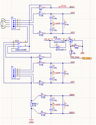
I am designing 4-channel measurement card for 4x RTDs (PT1000) with 4 wire measurement connection and i have question about my design of the input section for the ADS1248.

The pictures of schematic and some calculations are attached. RTDs will be class 1/3 DIN. The REF resistor will be something like PTF56 or something similar with low tempco.

The antialiasing filter in the input is same for all the inputs, so it is same for RTD meas input like for REF input. I added a resistor (maybe add a diode too?) in IDAC section and signal relay. So it is posible making something like "reconnection" when there isn´t first RTD populated.

And last, I am thinking about some additional protection for inputs like TVS, but they can make some offset due their leakage current. Maybe use Schottky diodes or something else?

What are you suggesting? Is this design of input section suitable for making some relativly good and accurate measurement of RTDs?

Thank you for hints, review and information.

  • Hi Jendas,

    So it is posible making something like "reconnection" when there isn´t first RTD populated

    I'm not really sure what this question is asking, can you please clarify?

    And last, I am thinking about some additional protection for inputs like TVS, but they can make some offset due their leakage current. Maybe use Schottky diodes or something else?

    I guess this would depend on the type of faults you want to protect against. If you are just concerned about miswiring faults, where someone could apply a constant voltage >AVDD to the ADC inputs, then simply having current-limiting resistors might be sufficient. If you are concerned about transients, then TVS diodes might be required as well. You can review our portfolio of low leakage TVS diodes for this purpose: https://www.ti.com/interface/circuit-protection/esd-surge-protection-ics/products.html#p2192=Flat-clamping

    The schematic image you sent looks pretty standard, other than the switch (AGQ210). Do you intend to measure the two RTDs in series as well as in parallel? The switch appears to be able to route the IDAC current to the lower RTD as well as connect the bottom lead of the upper RTD to the top lead of the lower RTD. If you do not need to measure the RTDs in series you could always use the IEXC1 pin to route the IDAC current to the lower RTD.

    -Bryan