This thread has been locked.

If you have a related question, please click the "Ask a related question" button in the top right corner. The newly created question will be automatically linked to this question.

DAC8775: Initial Programming

Part Number: DAC8775

There are two questions about DAC8775 initial Programming. 

1. Pls help to check if below setup is correct?

      DAC8775_WriteToRegister(0x01, 0x0001);     // Reset Register

      DAC8775_WriteToRegister(0x02, 0x0012);    // Internal Reference 5V、When power OFF, both IOUT and VOUT are high impedance

      DAC8775_WriteToRegister(0x06, 0x000F);   // Select Buck-Boost Channel ABCD

      DAC8775_WriteToRegister(0x07, 0x061F);    // Buck-Boost Set +15V ~ -15V

      DAC8775_WriteToRegister(0x03, 0x01E0);    // Select DAC Channel ABCD

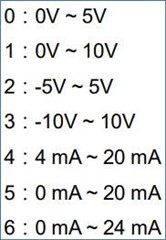
      DAC8775_WriteToRegister(0x04, 0x0000);   // Set for Voltage output 0 to +5 V (default) range

      DAC8775_WriteToRegister(0x04, 0x1000);    // Enable output

2. Are address 0x08 - 0x0A able to be calibration for each channel?

3. How to choice the each channel A B C and D? by address 0x3 or 0x6?

Regards

Brian 

  • Brian,

    I think this startup sequence works for the DAC8775. In general, you start the Buck-boost first, and then start programming the DAC. I generally like starting the reference first, to make sure it is ready before the DAC is operational.

    For calibration, each DAC channel can be calibrated individually. To do this you would first select the DAC you want to calibrate using the 0x03 (Select DAC Register). Then you write the calibration into the offset or gain registers (0x08, 0x0A). You can then select another DAC with 0x03, and then write another set of calibration values to 0x08 and then 0x0A. I believe that if you want to, you can write multiple registers with the same calibration values by selecting multiple DACs with 0x03. 

    For selecting DACs with 0x03, use:

    0x0020 - Channel A

    0x0040 - Channel B

    0x0080 - Channel C

    0x0100 - Channel D

    Joseph Wu

  • Thanks Joseph.

    here is a following question. Customer trying on the output test of the DAC8775. In the measurement on the customer board with DAC8775, the output current of 20mA below is accurate, but when it's >20mA, it could not achieve 24mA,max. why?


    What's the Configuration Buck-Boost Register (address = 0x07)

    Regarding to PCLMP[3:0] and NCLMP[3:0], what's the setting?

    In the system spec, there are 6 output models:

    Max. Voltage Range +-10V

    Max. Current Range 0~24mA

  • Brian,


    I am using a DAC8775EVM and I'm able to get 24mA output without any problems. How do they have their circuit set up? Are they using the internal reference or an external reference? What load are they using on the current output?

    The Configuration BB register (0x7) setting the default is 0x0000. As you turn on the BB, the register is set to 0x0003 for both the positive and negative sides. However when you turn out the DAC output with the BB on, the other bits of the 0x7 register can be automatically set.

    For example if the DAC output is set to voltage mode and enable the DAC output with the BB on, the NCLMP and PCLMP are automatically set to ±15V and the Configuration BB register reads 0x061F. If I put the device to current mode and enable the output with the BB on, the NCLMP and PCLMP are set to the lowest voltages of +4.0V and -5.0V with the CCLP set to 01 so that the user can set the values directly. Note that this setting allows the NCLMP to change depending on load through the adaptive power management. Regardless of what the VPOS_IN_x and VNEG_IN_x values, the NCLMP and PCLMP register values do not change unless the user sets them.

    If they do not have one, I would highly recommend getting a DAC8775EVM. It is a simple tool that allows changes in the registers, and you can easily see how the device reacts.


    Joseph Wu