This thread has been locked.

If you have a related question, please click the "Ask a related question" button in the top right corner. The newly created question will be automatically linked to this question.

ADS5474EVM: Connect with HSDC Pro

Part Number: ADS5474EVM
Other Parts Discussed in Thread: ADS5474

Hi Team,

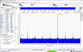
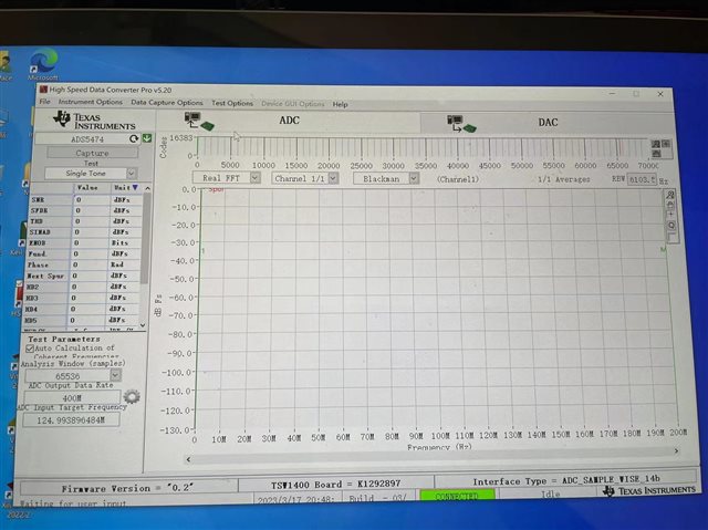
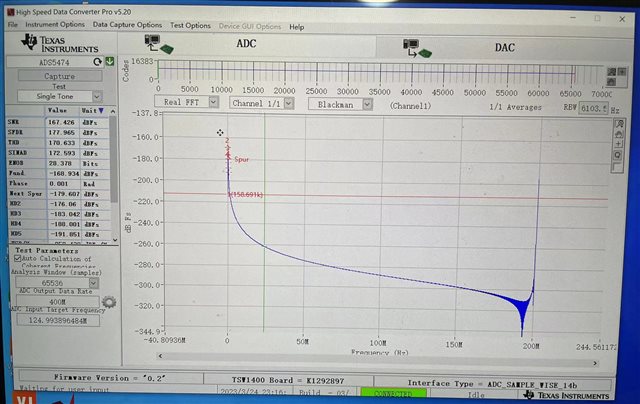
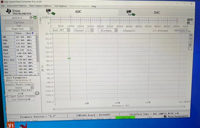
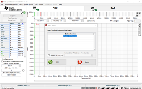
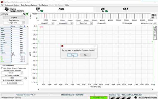
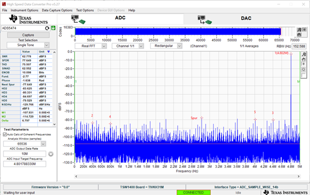
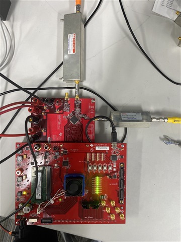
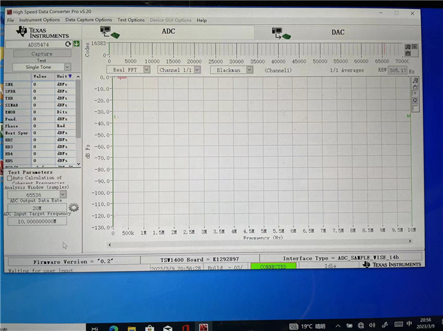
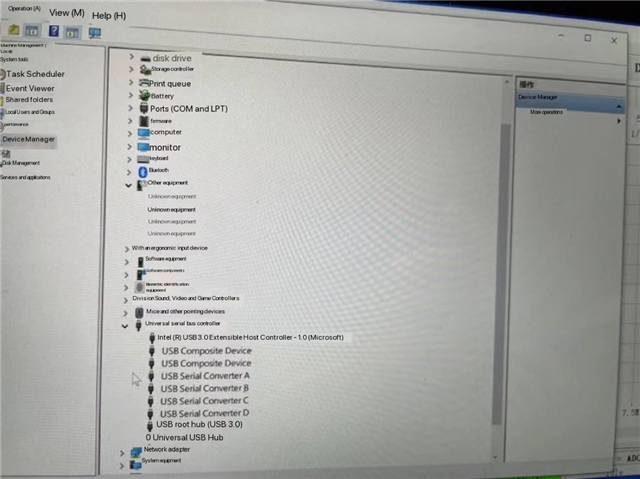
Our customer connected ADS5474EVM to TSW1400EVM and ran HSDC Pro. All LED except LED4 is bright, but he did not get any reading from HSDC Pro, not even noise. Please see the screenshots of HSDC Pro and device manager below.

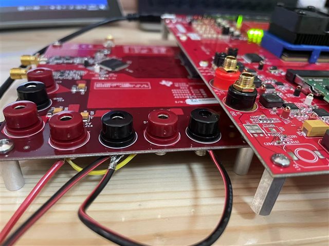
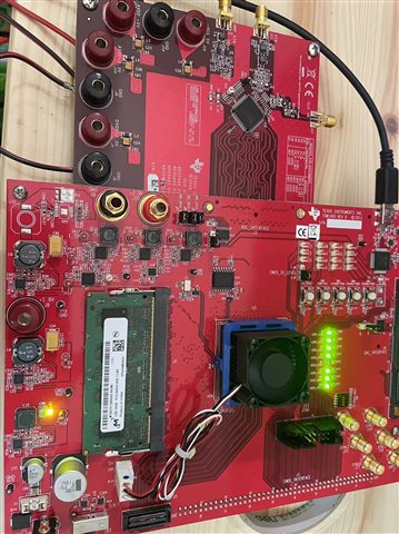
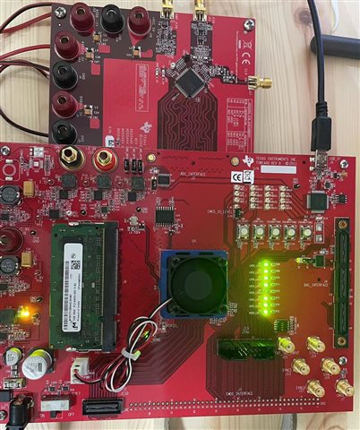
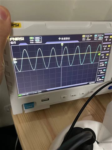
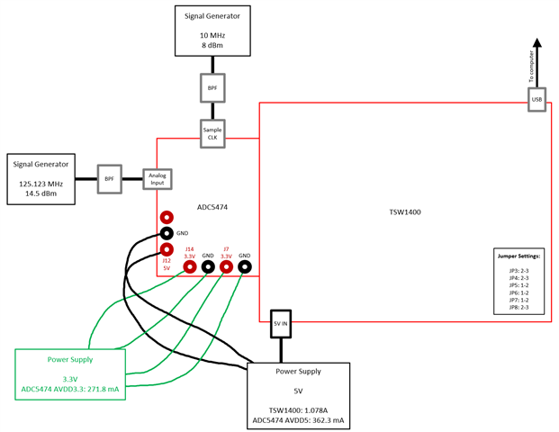
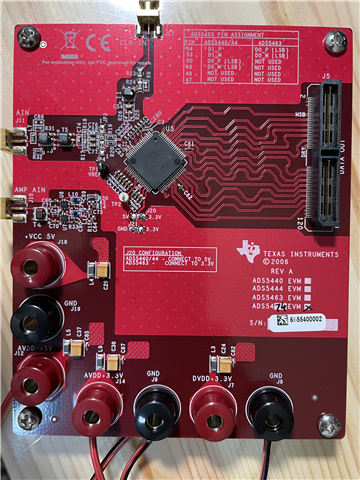
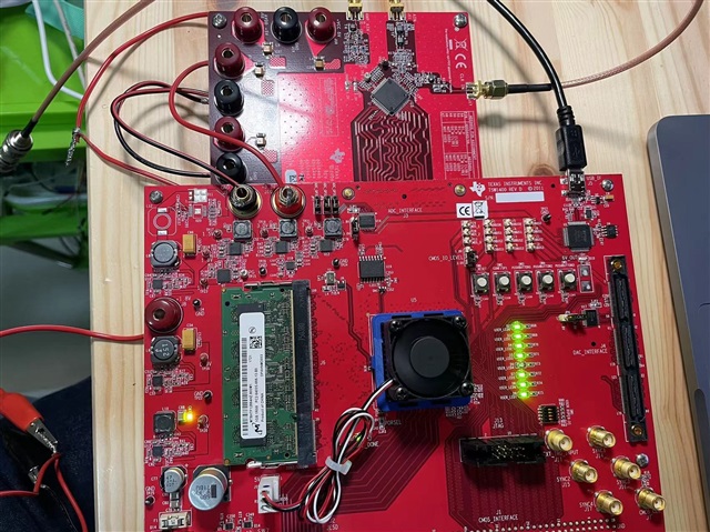
He also added that his application is to collect signal from a 200MHz current amplifier which is connected to a PMT. The parameter of amplifier is attached as well as the image of the boards. He would like to know how to configure the HSDC Pro and the jumpers at Table 1 of the User's Guide. Which input should he connect to, J11 or J10?
  
Regards,
Danilo
  • Hi Danilo,

    We are checking into this. Has the customer successfully gotten a capture in HSDC Pro before? 

    Regards, Amy

  • Hi Amy,

    Our customer bought the evaluation modules two weeks ago. This is the first time that they used the boards.

    Regards,

    Danilo

  • Hi Amy,

    We would like to request an update to this inquiry.

    Regards,

    Danilo

  • Hi Danilo,

    Please check that the customer is correctly powering the board. J12 should be 5V, J14 and J7 should be 3.3V. It appears that the customer is using the 3.3V from the TSW1400 EVM, but it does not appear from the image that J7 is connected (but it is hard to tell). The current draw should be ~270mA between J14 / J7. I cannot tell what they are using for their 5V source, but the current draw should be ~350mA. (I test this in the lab). All jumpers should be in the default configurations listed in the user guide. 

    Ensure that the customer can capture a noise floor before attempting a signal input. This is a dual channel device, please refer to pg. 19 in the user guide. One channel uses a balun (J11) and one channel uses amplifiers (J10). 

    Regards, Amy

  • Here is what I see on my end with an input signal to J11:

  • Hi Amy,

    In last email, the J14 and J7 was parallelled connected to 3.3 V from TSW1400. The J12 was connected to a 5V power supply as the TSW1400.
    There was still no noise obserserved.

    In the new configuration, the J14 and J7 was parallelled connected to 3.3 V independent power supply. The J12 was connected to a 5V power supply as the TSW1400.

    There was still no noise obserserved, as shown in the attached picture.

    What would be the problem?
    Regards,
    Danilo
  • Hi Danilo,

    Did the customer confirm that they are seeing current draws similar to what I tested on our lab EVM? (The current draw should be ~270mA between J14 / J7. The current draw should be ~350mA for the 5V source). Additionally, is HSDC Pro throwing any errors when they try to capture data? If so, please provide screenshots of these errors. One last question to confirm - have there been any modifications to the ADS5474EVM or TSW1400EVM?

    Regards, Amy

  • Hi Amy,

    Please see the update of our customer below.

    The  current for J12-J19 was about 316mA, the current for J14/J7 together was about 240 mA. The board was not modified. before I get no error from the HSDC, and the leds are lighting on TSW1400. but this time, I got no leds lighting and error about not find firmwares. No firmware, Please select a device to load into firmware into the board. One more thing as I mentioned before, the chip on ADS5474 generate a lot heat.

    Regards,

    Danilo

  • Hi Danilo,

    The current draw looks fine. Check your FPGA voltage supply to ensure the current limit is at least 4A to ensure the firmware can correctly install. In the photos you provided the firmware is correctly installed and the LED lights are correct. Try putting a fan over the chip to reduce the heat. 

    Regards, Amy

  • Hi Amy,

    Here is the feedback of our customer.

    I tried with a 5V 10A power supply, still didnot get any output, as shown in the attached figures.

    What would be the problem?
    Regards,
    Danilo
  • Hi Danilo,

    It appears that the customer was able to take a capture (the first image). Please check to see if they can get a noise floor without an analog input and provide the output HSDC Pro Capture.

    What is the customer using for a clocking source? Analog input source?

    Regards, Amy

  • Hi Danilo,

    Please ask the customer to please provide the clocking source output amplitude. As Amy indicated we need both model numbers of the clock and analog input sources.

    In some of the pics provided above, the customer doesn't always have the clock connected to the EVM. Please make sure that it is connected when taking a data capture. Its the only way the setup will work.

    Thanks,

    Rob

  • Hi Danilo,

    Additionally, have the customer probe the DRY and a couple of output bits on the ADC using a scope to see if these are active. It appears the TSW1400 may not be getting a clock from the ADC.

    Regards, Amy

  • Hi Rob and Amy,

    I received this update from our customer.

    Thanks a lot for your help.
    The clock I was using is 10MHz, 1.5V sine wave. Still I did not get the noise background from TSW1400.
    what is the right setting for testing the board?
    Regards,
    Danilo
  • Hello Danilo,


    To get a capture did the customer follow the below steps (I can see that he did from the pictures attached but would like to double check)?

    1. Connect the ADS5474EVM board to the TSW1400 board through J3 (ADC_INTERFACE) of the TSW1400 board
    2. Connect jumper cables to J12 of the ADC5474EVM board and set the power supply to 5V
    3. Connect jumper cables to J7 and J14 of the ADC5474EVM and set the power supply to 3.3V
    4. Connect a signal generator to SMA J17 on the ADC5474EVM board to provide CLKin source for sampling clock
      1. Set to your desired sampling rate frequency (which should be 10MHz from your previous reply)
      2. A sample clock must ALWAYS be provided to see a capture on HSDC Pro
    5. Connect a signal generator to SMA J11 on the ADC5474EVM to provide the analog input needed to be resolved
      1. If no signal is provided, only a noise floor will be seen on HSDC Pro
    6. Open HSDC Pro as administrator and you’ll get the below pop-up. Select “OK”:

                              a. If you don’t get the above pop-up, connect to the board by selecting “Instrument Options” -> “Connect to the Board”

    7. On the drop-down on the upper left-hand corner, select “ADS5474” and select “Yes” when asked if you want to update the firmware:

    8. Check “Auto Calc of…” checkbox, set your “ADC Output Data Rate” to “10M,” your desired ADC analog input frequency (I used 4.8M) so “ADC Input Target Frequency” to “4.8M,” (this will change to 4.801788330M since a prime number is needed to obtain optimal data) and select “Capture." Note that the balun in the EVM can only accept signals higher that 4.5 MHz.

              a. What is your analog input frequency?

    Apart from the above steps, please find a picture of my setup and a diagram that also illustrates it.

    Finally, if none of these steps displays a capture, could you probe the ADC5474 part on the EVM right at the pin of the sample clock (pin 10, positive, and pin 11, negative) an let me know if you see a signal? Thanks!

    Best,

    Andrea

  • Hi Andrea,

    According to our customer, he finally got an output from HSDC Pro. 

    Thank you very much for your help!

    Regards,

    Danilo

  • Hello Danilo,

    I'm glad the customer was able to get a capture. If possible, would you mind sharing what he did to resolve the issue and what was the issue? Thanks!

    Best,

    Andrea

  • Hi Andrea,

    The customer's ticket has been closed here at the CSC and it seems the solution you have provided solved the issue. 

    We really appreciate your help!

    Regards,

    Danilo