This thread has been locked.

If you have a related question, please click the "Ask a related question" button in the top right corner. The newly created question will be automatically linked to this question.

ADS131A04: Not getting responses with reference to values mentioned in datasheet

Part Number: ADS131A04EVM
Other Parts Discussed in Thread: ADS131A04

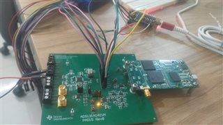
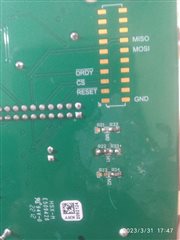
We need ADS131A04 for the development of our application, at present we are evaluation module which will ease the development process.

I am using STM32 L432KC development board using SPI to fetch the data in STM Cube IDE.

1. Operating modes set while system is powered off:

M0 - Asynchronous Interrupt mode ( Vdd)

M1 - 16bits (Gnd)

M2 - not connected (floating)

2. Reset pin EVM is connected to one of the GPIO pin. System reset is performed by set, reset and setting the gpio pin.

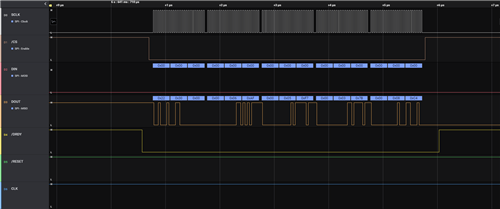
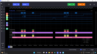
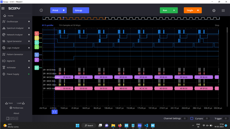
3. Then by sending NULL command, i am waiting for READY status word(0xFF04), but even after sending 2 successive null commands, I get FF82 itself. Somehow i manage to left shift and consider it as FF04.

4. Then I am sending UNLOCK command. Even if i send 0x655 , i am getting 80 19 80 response in Logic analyzer and in IDE the expression  will be ff82.

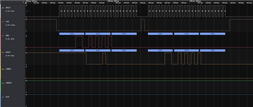
5. Same with all the other configuration registers. I am not getting exact data sheet suggested response for any of the command.

What am I missing? Any help from the team is greatly appreciated, as we are in really need of this device to be operated asap.

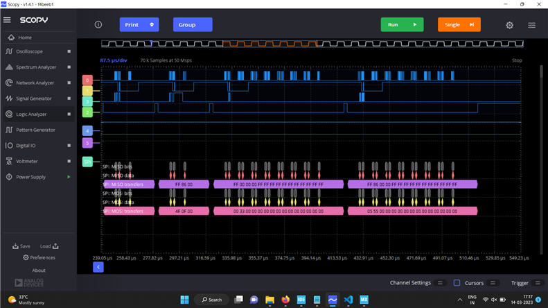
When I'm using the GUI using PHI connector with all the default values and with external ref voltage, i am able to read the ADC data. And i am trying to give the same default values which were in the GUI

Contd...

  • Hi Sri,

    I apologized for the late response, I'm still travelling now, I will check the details and get it back to you once I go back early next week.

    Regards,

    Dale

  • Hi Dale,

    Thanks for the reply. But it was quite critical for us. Can anyone else on behalf of you can look into this?

  • Hi Sri,

    I apologized for my late response. I'm not sure whether you still have the trouble or not. However, please refer to the following timing which were captured without the GUI control. 

    I double checked your description above, your M2 pin of ADC should not be floating. The data word size is actually not available when the M2 pin is floating. It seems 24-bit data size is expected by you, so your M2 pin of ADC should be shorted to the GND. please check the table 10 in the ADS131A04 datasheet. Please correct it and check again, thanks.

    Data capture for floating input:

    Unlock command:

    Best regards,

    Dale

  • Hi Dale,

    Unfortunately the problem has not yet solved and we have stuck at the same part.

    Also the necessary operating modes as suggested by you has been made as follows:

    M0 - Asynchronous Interrupt mode ( Vdd)

    M1 - 24bits (Gnd)

    M2 - Hamming Code Disable(Gnd)

    Though it is changed, the response for UNLOCK command is again FF04 in timing diagram of Logic Analyzer and in the code part it shows FF82.

    Any clock frequencies or settings need to be changed? Or shall I just share the code i am working?

    How to debug this problem

  • Hi Sri,

    I noticed you set the JP3 jumper to pin 2-3 position, this led to your AVSS to -2.5V, however the AVDD is 3.3V on the EVM by default, so your AVDD-AVSS-=5.8V for the ADC. I'm not sure if this is related to the issue you are facing, however, please put the JP3 jumper back to pin 1-2 and test again.

    Also, can you change your timing same as what I showed to you for both unlock and data capture? a closer look like what I showed will be better for me to check. Thanks.

    Regards,

    Dale