This thread has been locked.

If you have a related question, please click the "Ask a related question" button in the top right corner. The newly created question will be automatically linked to this question.

DAC7641: APPLICATION

Part Number: DAC7641

I have selected a DAC7641 to convert a 3 digit thumbwheel switch to a 0 to 2.99V analog signal. The DAC is powered with a single 5V supply as shown in FIGURE 2 of the datasheet.

  1. A microcontroller converts the 3 BCD switch outputs (0 to 299) to a 16 bit binary word.
  2. The binary word is multiplied by 219, i.e., 0 to 65481
  3. An existing 2.5V reference is used for this and other purposes in this design.
  4. The Vout of the DAC7641 drives an opamp with a gain of 1.2.
  5. The changes in the thumbwheel switches occur randomly.

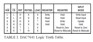
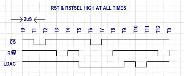
QUESTION: Is there a static setting of the digital interface that will change Vout without changes to the digital interface?

  • Hi Jack,

    Not sure I understand the question, but the output of the DAC will not change without some external excitation.  For example, changes to the voltage reference will cause the output to change proportionally.  Otherwise, digital inputs would need to change for the DAC to change (like RST getting asserted).

    Thanks,

    Paul

  • Paul,

    There aren’t many Frosts out there but that must make you one of the good guys like the rest of us. How did you avoid the Jack nickname, in my immediate family we all are known as Jack.

    In this design a microcontroller converts a 3 BCD digit (0-299) to a 16 bit binary word. The binary word is multiplied by 219 to shift the number to the higher order. The uC clock is 1MHz and the conversion occurs every 40 (estimated) uS.

    The digital interface can be added to the conversion coding but I don’t understand the sequence to get the Binary data to the DAC register after every data type conversion.

    QUESTION: What, if any, fixed value of the digital interface will connect the binary input to the DAC register?

    Regards,

    Jack

  • Hi Jack,

    My grandfather was "grandpa Jack" Slight smile

    Most of the digital inputs will need to be dynamic to update the output.  The CS, RW, and RST can be static.

  • Paul,

    If CS, RW & RST (RSTSEL?) can be static I clearly don’t understand the datasheet. I don’t have any reason to reset in this app so I’m assuming RSTSEL is a ‘don’t care’. That would leave LDAC as the only active signal necessary to transfer the binary word to the DAC register. Am I overcomplicating the issue?

    This is the timing as I interpret the datasheet.

    I don’t understand what the events in T10 to T12 serve, is the condition at T9 be the end of the sequence?

    Regards,

    Jack

  • You could consider the application where multiple DACs are on a shared bus.  IN that case, you would need a unique /CS signal to allow only the target DAC to be updated.  In addition, the R/W is used when the value stored in the device needs to be read back.  If you only have one device on the bus and only want WRITE capability, then CS and R/W are not really necessary.