This thread has been locked.

If you have a related question, please click the "Ask a related question" button in the top right corner. The newly created question will be automatically linked to this question.

ADS131B04-Q1: Output error

Part Number: ADS131B04-Q1

Dear team, 

My customer would like to use ADS131B04-Q1 to measure input current for Analog Input module application. but there is issue on output. 

They are using 2 device of ADS131B04-Q1 to check 8 CH input current (20mA). 

<Issue status> 

- Differential input : 20mA input per CH 

- There is no issue from 1st Ch to 7th Ch output but the last ch(8th ch) output is almost below 10mA. 

- If they set single ended input type not differential input, there is no issue all CH output. 

Below is input schematic per CH. please review below schematic and issue status. And let me know your opinion regarding 8th CH output issue.   
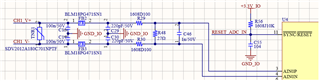
Thank you. 

  • Hi Dino,

    good to hear from you. I would have two questions first:

    • What do you mean by "single-ended configuration instead of differential input" in this case?
    • How do you make sure the common-mode voltage of the burden resistor is within the ADC input range? I don't see any ground connection on the burden resistor?
      So one explanation could be, that the common-mode voltage is outside the range of the ADC input and therefore the measurement is incorrect.

    Regards,
    Joachim Wuerker

  • Hello Joachim, 

    Thank you for your comment. Please refer to the below my comment. 

    What do you mean by "single-ended configuration instead of differential input" in this case?

    Single ended configuration mean that CHx V- are connected GND. If CHx V- connect GND , all 8 CHs output is correct. 

    But they are using differential input, only 8th CH output is abnormal. 

    So one explanation could be, that the common-mode voltage is outside the range of the ADC input and therefore the measurement is incorrect.

    If the common-mode voltage is outside the range of the ADC input, Why is the 8th CH output only incorrect? They are using  the same range at all 8 CHs input of ADC. Please let me know your opinion. 

    Thank you. 

  • Hi Dino,

    if they don't establish a known common-mode voltage - by connecting one side of the shunt to the same GND as the ADC for example - how do they know where the common-mode of that signal is? I don't think you get around that GND connection.
    My suspicion is that the common-mode of Ch8, for whatever reason, drifts outside the range of the ADC. They can try to measure the voltage on the positive and negative ADC input of Ch8 with respect to ADC GND with a DMM to check if it is within the specified range. However connecting the DMM might move the common-mode.

    Regards,
    Joachim Wuerker