Part Number: DAC63204
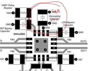
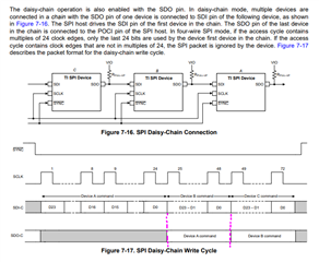
Hi, we have a hardware board with 8 daisy chained DAC63204 devices that are wired as in the attached picture. Each SDO pin is tied to VCC via an 1k pull up resistor and daisy chained to the second device in the SDI line.

The clock speed is 500khz and spi mode 1.
First we set the SDO_EN bit to 1 and the we configure the register to output 3.3V on ch3 of the device. We tried to over ride by programming each individual device and the devices respond according to the firmware .
When in daisy-chain mode the devices never clock the data past the first device in the line. Are there any other specific requirements to make the daisy-chain mode work?.
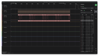
As a note: in the data sheet is specified that SDO pin needs an pull-up resistor while the SDI needs to be left floating, basically in the daisy-chain mode this being impossible.
The datasheet is also incorrectly label in the layout section as it follows: