This thread has been locked.

If you have a related question, please click the "Ask a related question" button in the top right corner. The newly created question will be automatically linked to this question.

ADS1261: Oscillation noise

Part Number: ADS1261

Dear Texas Instrument Team,

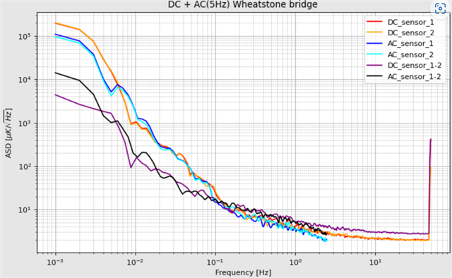
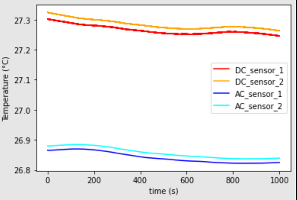
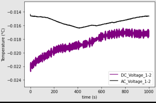
when doing the DC or AC measurement i see an oscillation in my signal (i guess it is crosstalk)

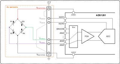
Ich exciting the DC and AC measurement with 5V and reading the signal with the AIN2/3 Pins.

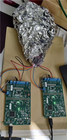
The attached photo below shows that clearly.

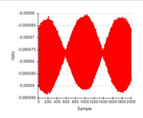
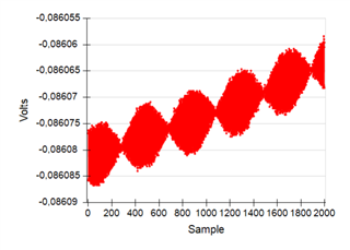
BTW i am measuring two (but same) Wheatstone bridge at the same time and both are showing oscillation but with different frequencies.

Best regards,

Marcel 

  • Hi Marcel,

    Can you please provide your schematic? Does 'Ich' mean '1ch'? Were these two photos measured on a same channel or different channels? thanks.

    Regards,

    Dale

  • ich = "i" but in my case i wanted to write "i am" :D

    I have two ADS1261 (see picture below) and two Wheatstone bridges which are wrapped in bubblewrap and aluminum foil.

    For the DC measurement i use the internal reference and for the AC measurement the AIN0/1 external as REF.

    Best regards,

    Marcel

  • Hi Marcel,

    Thank you for providing more information. The following block diagram should be your connection for AC measurement with external 5V Vref as you said, please correct me if my understanding is wrong. Have you tried different data rate and filter options to check the result? I'm not sure if the local 5V power supply on the EVM is good enough as an excitation source for you bridge because all of power supplies on the EVM come from the USB port.

    The primary support engineer for this ADC is on vacation this week and he will come back next Monday, he may be able to do some tests for you if you can wait for him to come back.

    Best regards,

    Dale

  • Dear Dale,

    the schematic you showed above is exactly my setup. I have used the AIN2/3 ports but that shouldn't make a difference, right?

    What else should i use for the the power supply? 

    When doing the DC measurement i can see the point in not using the onboard power supply,

    but when doing the AC measurement with the 4-wire-AC-excitation, how else should i implement it. 

    Isn't the board switching the polarity during the AC-excitation to make the measurement possible in the first place?

    Is there any way to lower the 5V output voltage? I wanna see if the oscillation decreases with less power = less crosstalk.

    Best regards,

    Marcel

  • Hi Marcel,

    AC excitation helps to reduce system-level offset and offset drift from a bridge measurement. The AC excitation method (or bridge chopping) usually uses external switches to swap the bridge excitation voltage polarity. I would recommend you to check my colleague's application notes to get the details: 

    There is also a script demonstrating AC excitation as one of the predefined scripts in the GUI. For AC excitation you should be following the script example.  The bridge control is using 4-wire AC excitation mode and only using ACX1 and ACX2 GPIO signals for control (GPIO set to AIN4 and AIN5 as per script). In the end there should be no oscillating output signal as even the AC excitation is still a DC measurement. 

    The circuit in the block diagram shows the connection for a ratiometric measurement as you use the same source for both excitation voltage and reference voltage, however your have selected internal AVDD and AVSS in REF register for the reference, actually you have to select external reference for a ratiometric measurement. Also, you did not set a gain in PGA register for the small bridge signal. The ratiometric measurement can eliminate the noise or change on the reference/excitation voltage, but it can not cancel the error from the leads and the device, however it should work as long as you have a correct configuration for the ADC.

    Best regards,

    Dale

  • I wanted to use the AC excitation only from the board since it is offered, ... but if you say that it is worse compared to to external switches then i will try those.

    Regarding the DC measurement: 

    - I still have and oscillating output

    - Should i use an external DC-power-supply instead of the board ?

    - Should i set a gain to increase the output voltage ? Does it decrease the noise ?

    Best regards,

    Marcel

  • Hi Marcel Beck,

    Do you get the same oscillations when you try to measure 1x bridge without using AC excitation? It will help to start with the "simplest" implementation, then get more complex from there.

    As Dale mentioned, there is a script that should implement AC excitation using features on the EVM. Once you get 1x bridge without AC excitation working, I would try using this script to see if you can get AC excitation working on the same bridge. If you are getting oscillations, it would appear something is not hooked up correctly (note that "AC excitation" in this case is a misnomer, there is no AC signal being generated and you are only using a DC voltage to excite the bridge).

    -Bryan

  • yes i am also seeing the oscillation when only measuring one bridge with DC.

    Like it wrote, the oscillation frequencies are changing over time (roughly 0.01 - 1 Hz) and are present in both bridges (one powered, the other one powered and both powered at the same time).

    Lets asume i can get rid of the osci, my next questions is:

    "Is the onboard AC-Excitation better (less noise) or should i use external switches like MOSFETS ?"

    For now i am only using the onboard ac-excitation and i can't see an improvement when comparing it with the DC-excitation.

    The following plots are showing the results of both measurements. (ASD + time series)

    The data of sensor 1&2 where taken at the same time.

    The plot below in the left side shows the difference when substracting sensor1 one from sensor2 (time series). 

    The sensors are wrapped in bubblewrap, aluminum foil and taped to the same aluminum plate.

    Best regards,

    Marcel Beck

  • Hi Marcel Beck,

    If the AC excitation feature does not improve the system performance, then I would not use it

    The noise you are showing looks like 1/f noise, or temperature drift. If you are indeed taking measurements over 1000 seconds (16 minutes), then you might see this effect.

    If you measure a "noiseless" input source e.g. a 1.5V battery, do you see the same issue?

    -Bryan

  • Hi Bryan,

    if i want to measure ADC noise what exactly do i select as the REF and the INPMUX?

    REF: AVDD & AVSS

    INPMUX: internal VCOM & internal VCOM          is this the way to go and shorten the inputs?

    My Goal is to measure a noise floor of my temperature sensor for low frequencies (<1Hz). Is is a good idea to just use my inputs (AIN1/2) without an applied voltage and the REF: AVDD&AVSS  to get the noise limit ?

    Best regards,

    Marcel 

  • Hi Marcel Beck,

    To measure the ADC noise, you would short the ADC inputs together, typically to mid-supply. So in this case, shorting to VCOM is a good idea.

    A shorted input noise test includes effectively zero reference noise, because there is no input signal. So it probably doesn't make a huge difference as far as which reference you use for these tests. However, the ADS1261 datasheet uses the internal 2.5V reference, so choosing this reference will allow you to directly compare your results with those from the datasheet.

    Again, this test will give you the ADC noise (including the integrated PGA), which is an effective limit on how low the system noise can be. Once you add in your sensor and start taking nonzero measurements, you will introduce sensor noise and reference noise as well (possibly other sources) that will increase the noise floor.

    -Bryan

  • I tried to repeat the measurements from the table above. (5SPS, SIC3,...)

    My results (figure below) are showing pretty much the noise from the datasheet. The ADC Conversion  Data Code i used is:

    Code = Code * V_ref */ (Gain * 2^23 )      Is this the right way to convert  ?

    Is V_ref=5V or 2.5 V when REF: AVSS AVDD and INPMUX: VCOM  ?    I think it should be 5V since the difference of AVSS & AVDD is 5V but i could be wrong.

    Are the blue plots my noise limit before connecting the sensor?

    Best regards,

    Marcel

  • Hi Marcel Beck,

    In the formula you are using, you have "code = code ...". I assume this is "code (in Volts) = code (in decimal) ..."

    VREF is 5V when REFP = AVDD and REFN = AVSS because VREF = REFP - REFN

    Correct, the blue plots are the noise of the ADC at the different "gain + data rate + filter type" combinations. If you externally short two terminals at the input of the PCB e.g. AIN0 and AIN1, then you would get the noise of the board including the signal conditioning circuitry, which in this case is really just the anti aliasing filters

    -Bryan

  • Yes is it code(volt)=code(dezimal) * V_ref */ (Gain * 2^23 )

    Is my conversion formula right?

    best regards,

    Marcel

  • Hi Marcel Beck,

    Yes this is correct

    -Bryan

  • i still quite dont get what exactly is connected when doing the test from the datasheet (table).

    for my REF i use AVDD & AVSS    (=5V)

    for my IMPMUX is use MUXN: Vcom   &   MUXP: Vcom          

    I measure noise at zero volt. Why am i not meauring noise at 2.5V sind the Vcom is (AVDD-AVSS) / 2   ?

    i get a factor of 2 less noise if i choose MUXN: Vcom   &   MUXP: AIN0      (or AIN1,2,3...) why is that so ?


    Another question is why do i get a drop down when getting close to the sampling rate/ (nyquist) only for Gain>1 ?

    The following measurements (only the ADC_noise_...) are taken with REF AVSS & AVDD while the INPMUX and the Gain is changed.

    Thanks in advance and best regards,

    Marcel Beck

  • Hi Marcel Beck,

    What do you have connected to AIN0, AIN1, etc.? I am not sure why the noise is different / better

    I don't see a drop down getting close to the sampling rate, except for those plots where you have the sensor connected. Also, please keep in mind that the ADS1261 is not a Nyquist converter, so it is sampling at a much higher rate than the data rate. This higher rate is called the modulator frequency (fMOD) and is approximately 1 MHz on the ADS1261

    How are you generating these noise density plots? I assumed you would just use the noise values provided the ADC GUI, especially since you are measuring a DC signal

    -Bryan

  • AIN0, AIN1 are connected to the sensor but with zero voltage supply (in theory you could also disconnect the sensor but in still wanted to check if any noise is coming from the sensor even though there is no voltage applied).

    I use the noise values proved by the ADC GUI. The data is afterwards converted in python with our linear spectral density.

    The plot below shows all of the measurements i mentioned above. The only difference is the INPMUX connection.

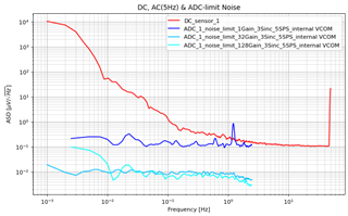
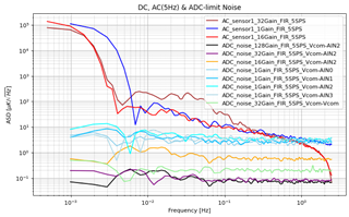
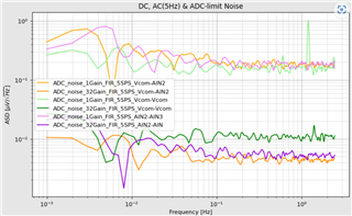
     The measurements for Vcom/Vcom are in good agreement with the data sheet (manual).

    Why are the measurements for the Vcom/AIN2 and the AIN2/AIN3 showing lower noise?

    Best regards,

    Marcel

  • Hi Marcel Beck,

    What is connected to AIN2 and AIN3 then?

    I am not really sure why the other configurations are lower noise. If shorting both inputs to VCOM yielded datasheet-level noise, there is no real reason the noise should be less than the datasheet. The datasheet noise is really the lowest possible noise the ADC can provide, unless additional averaging is performed.

    Can you send me screenshots of the ADC GUI showing the noise results for each configuration? Also please let me know what reference voltage you are using and which gain, assuming it is not obvious from the screenshots.

    -Bryan

  • AIN2/AIN3 are still connected to the sensor but there is no voltage supplied, so basically there is "nothing" connected.

    My REF is the AVSS/AVDD

    All other configurations are the same only INPMUX is different.

    But since you are saying the data sheet values are the lowest noise possible i have a well measured noise-floor i can work with.

    Thanks for all the anwers and BTW nice work on the Fundamentals of Precision ADC Noise Analysis, helped alot understanding the basics.

    Best regards,

    Marcel

    Maybe one more question:

    I also connected Vcom/AIN2               Vcom=2,5V   and my potential of AIN2= 0V (nothing is connected)

    Shouldn't there be a voltage of of 2,5V ? I am measuring the 0V noise (yes i checked the time series since the ASD from last answer is only showing a change).

  • Hi Marcel Beck,

    If AINP = 2.5V and AINN = 0V, then yes you should measure a differential voltage of 2.5V. Note that in this case AINP and AINN can be any analog input.

    -Bryan