This thread has been locked.

If you have a related question, please click the "Ask a related question" button in the top right corner. The newly created question will be automatically linked to this question.

ADS1298 - Lead-off Detection

Other Parts Discussed in Thread: ADS1298, TMS320VC5505, ADS1298ECGFE-PDK, ADS1258

Dear All,

I am a little confused about the lead-off detection schemes of ADS1298. My understanding of enabling lead-off detection is as given below. Please correct me if I am wrong.

  1. Enable Lead-off detection by settings Bits[1:0] of LOFF register to 01(AC mode) or 11(DC mode)
  2. Set detection mode to pull-up or current source more byte setting Bit4 of LOFF register.
  3. If current source mode is selected, set the current by setting Bits[3:2] of LOFF appropriately.

Is current source mode or pull-up/down mode applicable only when using DC lead-off detection?

I understand that in AC mode (pull-up or current source config), a signal of Fdr/4 is injected into the lead and the presence of the same is checked at the output to see if the lead is intact. Now in AC mode, does ADS1298 update the lead-off status register by itself or do I need to put frequency detection code in my software to check for the presence of lead-off excitation signal? If it sets the registers by itself, what is the criterion for setting the comparator thresholds?

Secondly when using AC mode, does any inverted excitation signal need be given to RL electrode external to ADS1298, or does ADS1298 does that by itself? If neither how does the signal vary when the electrodes are in place and removed?

  • **TI EDIT February 20th 2019; FOR GENERAL ADS129x ASSISTANCE, PLEASE SEE NEW BIOPOTENTIAL FAQ LOCATED HERE**

    Hi Horizon,

    I'm trying to put together a better description of the lead off detection based on DC versus AC modes of the ADS1298.  I'll try to have something posted for you on our ADS1298 FAQ page later today or early tomorrow.

  • Thank you Tom, will be looking forward to it.

  • To Enable Current Mode DC lead-off detection

    1.    Enable Lead-off detection by settings LOFF[1:0]=11(DC mode), LOFF[3:2]=11, LOFF[4]= 0, LOFF[7:5]= 111(for example).

    2.    Apply input signal to comparator by setting LOFF_SENSP and LOFF_SENSN register bits.

    3.    Enable lead off comparators by CONFIG4[1]=1. 

    4.    LOFF_STATP and LOFF_STATN registers will register the output of the lead off comparators.  Comparator outputs should be disregarded if LOFF_SENSP and LOFF_SENSN are LOW.  Enabling the bits in these registers connects the switch to the input of the comparator.  If you have comparator on, but input floating. The output will toggle sporadically. 

    To Enable Resistor Mode DC lead-off detection

    1.    Enable Lead-off detection by settings LOFF[1:0]=11(DC mode), LOFF[3:2]=11, LOFF[4]= 1, LOFF[7:5]= 111(for example).

    2.    Apply input signal to each comparator by setting LOFF_SENSP and LOFF_SENSN register bits.

    3.    Enable lead off comparators by CONFIG4[1]=1.  This is a global enable, all 16 will turn on.

    4.    LOFF_STATP and LOFF_STATN registers will register the output of the lead off comparators.  Comparator outputs should be dis-regarded if LOFF_SENSP and LOFF_SENSN are LOW.  Enabling the bits in these registers connects the switch to the input of the comparator.  If you have the comparators on, but input floating the outputs will toggle sporadically. 

    Q: Is current source mode or pull-up/down mode applicable only when using DC lead-off detection?

    A:  Yes that’s right.

    Q: I understand that in AC mode (pull-up or current source config), a signal of Fdr/4 is injected into the lead and the presence of the same is checked at the output to see if the lead is intact. Now in AC mode, does ADS1298 update the lead-off status register by itself or do I need to put frequency detection code in my software to check for the presence of lead-off excitation signal? If it sets the registers by itself, what is the criterion for setting the comparator thresholds?

    A:  The lead off status registers are only for DC modes, not AC.  For AC lead off, you will need a bandpass filter to determine the signal and determine if lead is off or not.  See attached slides. 

    Q: When using AC mode, does any inverted excitation signal need be given to RL electrode external to ADS1298, or does ADS1298 does that by itself? If neither how does the signal vary when the electrodes are in place and removed?
    A:  The third slide shows the results of how it works.  The AC lead off signal will be small and increase as the impedance gets larger. 

    There is a little bit of an explanation for how to go about this in the ADS1298ECGFE-EVM Users Guide as well on page 53.

    ADS1298_AC_LeadOff.pdf
  • Thank you for the neat description Tom. You did tickle my brain and now I have a couple of more questions!

    Limitation of AC Lead-off Detection

    Lets say, while in AC lead-off detection mode, my RA electrode is dislodged. This would cause the excitation signal to appear on both Lead I and Lead II since Lead I = LA - RA and Lead II = LL - RA. The situation will be similar when either or both of LA and LL are also left floating. Hence it would be difficult if not impossible to judge which all leads have come out. Similarly, the removal of any combination of LA, RA or LL would cause the excitation signal to appear on all the chest leads! Theoretically it may be possible to identify the electrodes that have been pulled our by measuring the p-p voltage of the excitation signal that has been extracted from each lead. However this voltage is also dependent on the electrode-skin impedance which cannot be guaranteed to remain a constant for even the same subject. Hence AC lead of may be usable only to warn the removal of any electrode.

    Q: Is this limitation true or can AC method me used to precisely identify which all electrodes are pulled out (except RL electrode of course)?

    Using DC Methods while Acquiring

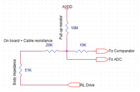
    With the feared limitation of AC lead-off detection, how good are the DC methods (current or pull-up.down) while acquisition is active? I remember this from somewhere that the DC methods cannot be used while acquisition is active. Please see the piece of schematic attached (derived from Application Report - SPRAB36A – July 2009 - ECG Implementation on the TMS320VC5505 DSP Medical Development Kit (MDK)).

    Due to continuous feedback, the RL drive establishes a potential of 0 (theoretically) at the point where the electrodes are placed. Since both comparator and ADC have relatively huge input impedance, the pull-up resistor and on-board resistance can be viewed as part of a voltage divider network. Hence when the electrode is connected, the voltage at the mid-point of these two resistors would be 5mV for AVDD=2.5V and given value for resistors. This falls well within the common mode as well as differential mode of the ADC. Now when the electrode is off, there is no particular current path except the infinitesimally small leakage currents, and close to full AVDD appears at both comparator and ADC inputs.

    Q: Is this theory true in case of ADS1298 with DC pull-up/down or current source methods of lead-off detection so as to use them while acquiring, or are these modes available only when the ADC is not acquiring?

  • Mohith,

    We have customers currently using AC or DC lead off methods to continuously determine which leads are off.  There are differences between the lead off detection of the discrete ADS1258 solution and the fully integrated solution found in the ADS1298.   Have you by chance gotten one of the ADS1298ECGFE-PDK setups and a simulator?   We'll try to put together a little tutorial explaining the process...

  • Tom,

    I haven't had a chance to get dirty with the PDK but I am making my own test board with help from PDK schematics. Should have the results in a couple of weeks. Currently my plan is to go ahead with current source mode for the better input impedance it gives. Since it doesn't require any external components to switch between the three modes, I am hoping to study in detail about all three using the same board.

  • Hi I have one question, I am using the following configuration.

    All channels are in input shorted, 

    And I am using LEAD OFF detection

    LOFF=0x13 DC pull up/down

    CONFIG4= 0x02

    LOFF_SENSP=0XFF

    LOFF_SENSN=0XFF

    So all channels are preaperd for lead off detection, all channels are disconnected.

    The question is the following the status output will be something like this 1100 + 11111111 + 1111111 GPIO, and I dont have that output, tha values changes so much.

    I think maybe is the noise at the input.

    Another Qestion  LEAD OFF detection  is only for used in electrode mode? 

    Thanks a lot.

  • Hi Oscar,

    We are in the final draft stages of writing an app note explaining AC/DC lead off and uses with the ADS1298. In the meantime, I recommend giving this post a read -

    http://e2e.ti.com/support/data_converters/precision_data_converters/f/73/t/124326.aspx#464964

    It is important that the RLD electrode is connected during lead off testing. Otherwise, the result will be a poorly defined common mode which may cause DC lead off to behave incorrectly.

    To answer your last question - DC LEAD OFF detection used with the comparators is run independent of the channel mux. Meaning that you can have the mux for all the channels set to test signal and the comparator bits in the STATUS BYTE will still update depending on the status of the inputs. I guess your answer would be 'No, LEAD OFF works regardless of what mode the input channels are set to"

    -Tony

  • Hi Tom,

    Could you describe which registers do we have to set for AC lead-off detection?

    Is it only the LDOFF[0;1] (FLEAD_OFF to 01)?

    Thanks