This thread has been locked.

If you have a related question, please click the "Ask a related question" button in the top right corner. The newly created question will be automatically linked to this question.

DAC8742H: About power consumption of DAC8742H and DAC8740H...

Part Number: DAC8742H
Other Parts Discussed in Thread: DAC8740H, DAC161S997EVM, DAC161S997

Hi Team,

Please help to advise the power consumption of DAC8742H and DAC8740H.

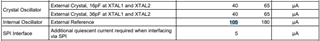
In the datasheet, there is only statement for the external crystal, still need for the internal oscillator.

Since DAC8742H supports UART and SPI mode, also need to know for this 2 mode power consumption.

And, please also help to review customer schematics as attached and provide you comments if there is anything wrong. 

Thanks.

DAC87XX & DAC161S997 - Schematic.xls

  • Peter,


    The currents are all listed in the datasheet, but it is not described very clearly,

    For all HART mode operation AVDD and IOVDD current consumption on page 8 of the DAC874xH datasheet and page 6 of the DAC8742H datasheet, these describe UART communication. If the SPI interface is used in any of these devices, then it requires an additional 5 uA of current. Note that the DAC8740H only has UART.

    For the internal oscillator, the current consumption is listed just below the value for the crystal oscillator. The 105uA is the extra current required above the demodulator active or modulator active values to run the internal oscillator.

    I'll need a little extra time to review the schematics.


    Joseph Wu

  • Peter,


    Looking at the schematics, I only see a few changes that should be made.

    For the DAC8742H schematic, there is a reserved section for the external bandpass filter. The top of R203 should be placed on the reference voltage of 2.5V. The R203/R204 is a voltage divider used to set the dc voltage of the HART input signal. If it is connected to 3.3V then the input will be set to the wrong voltage.

    For both the DAC8740H and the DAC8742H, REG_CAP should not be used as the reference. The REG_CAP pin is used as an external capacitor connection for an internal LDO.

    For the DAC161S997 schematic, R196 connects the VD and VA pins. It should not be 100kΩ. If they want to use a resistor, they can use the 20Ω value that is used in the DAC161S997EVM. Also, the npn transistor they use is the MMBT3904. This pulls the current from the loop and can be a significant amount of current. If you look at the EVM, they used the PZT3904, which is capable of dissipating more power. In addition, the EVM uses a 3.9V Zener diode at the collector of the npn. This Zener reduces the collector-emitter voltage of the npn, and therefore reduces the power dissipation.


    Joseph Wu