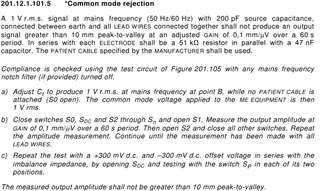
Hi,
I have some questions about the input noise and CMRR of ADS1299:
1.I use the development board TI recommended PC software test development board CMRR
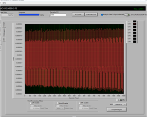
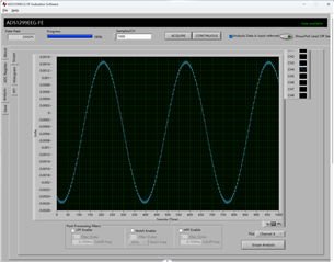
(1)The P and N electrodes are short-connected. The input signal of the signal source is 0.2Vpp/50Hz, PGA=1. The output signal of channel 2 is shown in the figure below.
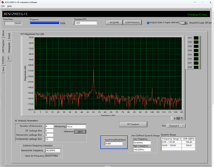
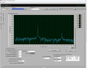
(2)The P and N electrodes are short-connected, the input signal of the signal source is 0.2Vpp/50Hz, PGA=1, and the FFT interface is shown in the figure below.
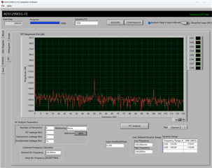
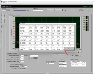
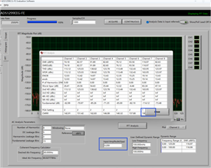
(3)The P and N electrode are short connected, the Input signal of the signal source is 0.2vpp /50Hz, and PGA=1. If the Input Amplitude is input 0.2, click the FFT Analysis button to obtain the CMRR of channel 2 =180dB (Channel 2 is configured, and CMRR is displayed in channel 7), as shown in the figure below.
2.I use development board TI recommended PC software test development board noise
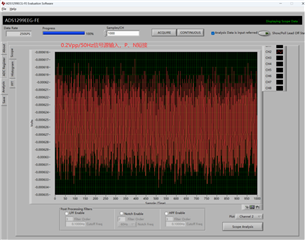
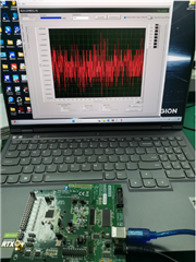
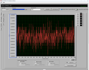
(1)Only power supply to the development board, and then use the upper computer provided by TI to observe data;
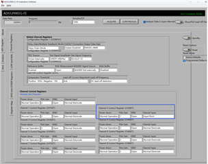
(2)Software configuration:
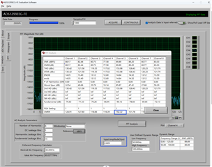
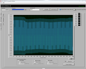
(3)The peak value of noise in channel 2 is 7uVpp:
3.How to measure the input impedance of the whole board?
CMRR=180dB, the noise is 7uVpp, which makes me very confused, is there something wrong with my configuration, or can I provide the correct test method?
Regards,
Dolf