This thread has been locked.

If you have a related question, please click the "Ask a related question" button in the top right corner. The newly created question will be automatically linked to this question.

ADC3643EVM: J1 and J3 connections

Genius 15149 points
Part Number: ADC3643EVM

Hi Experts,

Good day. Seeking your assistance on this request clarification for ADC3643EVM:

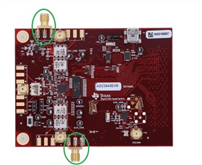
On the product page appears an image where SMA connectors J1 AND J3 are soldered in PCB. In the design tool zip file there is a note where it says that this connector is not soldered. What's correct?


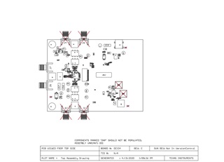
Customer wants to add that we need to enter to the ADC without any high-pass filter or similar, we need to digitalize a unipolar signal. In schematic, the SMA connectors J1, J3 J4 and J6 seem that they jump the transformer filter section.

Thank you for your assistance.

Regards,
Archie A.

  • Hi Archie,

    The photo of the EVM is correct - the two SMA connectors are populated on the ADC3643EVM. The J1/J4 connectors would be used if the customer wants the board in amplifier configuration; the J2/J5 connectors would be used if the customer wants the board in balun configuration. The amplifier configuration has a 20MHz LPF and the balun configuration has filtering modifiable for the application.

    Regards, Amy