This thread has been locked.

If you have a related question, please click the "Ask a related question" button in the top right corner. The newly created question will be automatically linked to this question.

AFE4403: Data converters forum

Part Number: AFE4403

Hello, I have a Question about the waveform by AFE4403EVM and AFE4403 Chip.

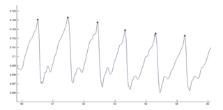
Waveform by AFE4403EVM:
                                         

Waveform by AFE4403 Chip on my custom made PCB Board:
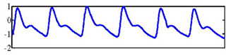
                                                     

I made all the connection according to schematic given in EVM guide to make my custom PCB Board and I am using DCM-10 PPG sensor.

Why both the waveform are inverted to each other. 

  • Hi,
    That is how the chip is designed. And, I think you or people from the same institution asked same questions before.
    All the info and answers were provided in this thread
    e2e.ti.com/.../4575373
    Thanks

  • Hi,
    That is how the chip is designed. And, I think you or people from the same institution asked same questions before.
    All the info and answers were provided in this thread
    e2e.ti.com/.../4575373
    Thanks

  • Hi, I understood the reverse wave phenomena by AFE.
    I think, you did not get my question,I am saying that, when I used the same firmware and code on the EVM it give me the result shown in first picture but when I used it with Custom made PCB using AFE4403 chip, the wave is similar to 2nd figure.(NOTE: I am not subtracting raw PPG data with any threshold and using every parameter same as I used for EVM board).

  • Hi,
    What might be your question?
    Are you asking why you get different waveform between a customer PCBA+customer's firmware and EVM+EVM's GUI?
    Which waveform do you want to work with?

    Thanks

  • Hi,
    I want to ask  why I am getting different waveform between my own custom made PCB+nRF52 microcontroller and AFE4403EVM+nRF52  when I am keeping every parameter same?

    Moreover, any waveform is fine, but I want to know the reason behind this difference. when I connect EVM with my microcontroller, it gives me an inverted PPG waveform as shown in first picture, and when I connect same microcontroller with same code on my own custom made PCB using AFE4403YZPR chip, output waveform is like 2nd Picture shown above. I did not find anything about it neither in AFE4403 EVM guideline nor in AFE4403 datasheet. 

  • Hi,
    Let me make sure I understand you correctly.

    When you us your own microcontroller and firmware(let's call this MCU1+firmware1) and

    Connect (MCU1+firmware1) to the AFE4403EVM, you saw PPG waveform as the 1st picture?

    Connect same (MCU1+firmware1) to your own AFE4403YZPR PCBA, you saw PPG waveform as the 2nd picture?

    Do I understand correctly?

    --------------------------------------------

    How and where did you get the plot? are the tool or software used to plot the same?

    Thanks