Hello everyone !!
I'm doing a Bachelor Thesis on the control of a special device with a DAC so I wanted to first test the controlling of the DAC with my Arduino MKR Vidor 4000 board.
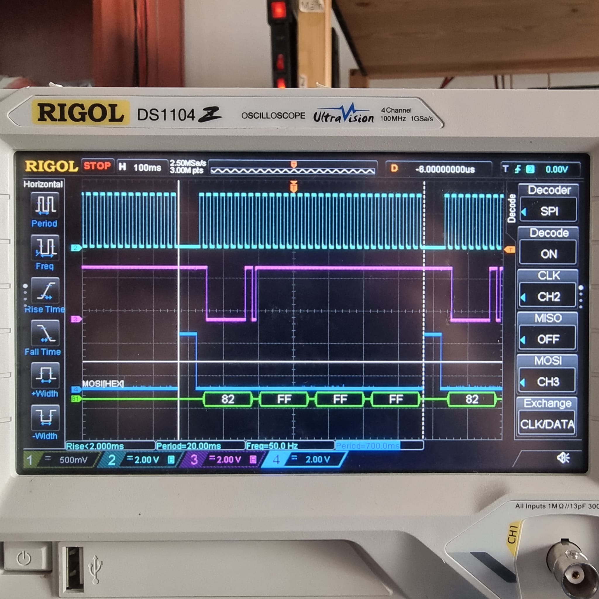
I have tested the SPI communication of the code with my Oscilloscope and everything seems to be in order but when I try to communicate with the DAC Evaluation Board it doesn.t work.
The following code is the one I wrote:
/* Inclusion of libraries */
#include <Arduino.h>
#include <SPI.h>
/* Defines */
// #define MOSI_PIN 8U //MOSI
// #define MISO_PIN 10U // MISO
// #define SPI_CLOCK 9U //SCLK
#define CHIP_SELECT 7U //CSz
// #define LDAC 0U //LDAC
// #define CLR 6U //CLR
/* Variable declarations/instanciations */
uint32_t speedMaximum = 2000000; // Maximum data transfer speed of the DAC is 50MHz but we cannot go further than 1MHz for now
uint8_t dataOrder = MSB_FIRST; // Bit 32 is the first bit to be sent in the data transfer packet
uint8_t dataMode = SPI_MODE1; // CPOL = 0 & CPHA = 1
byte myData[4] = {0}; // Data buffer
/* Function declarations */
SPISettings mySettings(speedMaximum, BitOrder(dataOrder), dataMode);
void sendData(byte byteData1, byte byteData2, byte byteData3, byte byteData4);
void sendByte(byte firstByte);
// void resetDAC(void);
void setup()
{
/* Open Serial Monitor */
Serial.begin(9600); // Debug monitor
/* Setting up the SPI pins*/
SPI.begin(); // Initializes the SPI bus by setting SCK, MOSI, MISO, and SS to outputs, pulling SCK and MOSI low, and SS high.
/* Setting up the CS pin */
pinMode(CHIP_SELECT, OUTPUT);
// /* Setting up the LDAC pin */
// pinMode(LDAC, OUTPUT); // LDAC pin as Output
// /* Setting up the CLR pin */
// pinMode(CLR, OUTPUT); // CLR pin as Output
}
void loop()
{
// digitalWrite(LDAC, HIGH); // Disable the LDAC pin which is active low
// digitalWrite(CLR, HIGH); // Disable the CLR pin which is active low
/* Starting the SPI bus */
SPI.beginTransaction(mySettings); // Start using the SPI Bus with this set of parameters
/* DAC get started code */
/* First set of bytes sent to the slave to setup the DAC */
// sendData(0x02, 0x00, 0x4C, 0x80);
// /* Second set of bytes sent to the slave to put 0 to the DAC */
// sendData(0x01, 0x00, 0x00, 0x00);
// /* Third set of bytes sent to the slave to put 524288 to the DAC */
// sendData(0x01, 0x7F, 0xFF, 0xF0);
// /* Fourth set of bytes sent to the slave to put 1048576 to the DAC */
// sendData(0x01, 0xFF, 0xFF, 0xF0);
// sendByte(0b10111100); // Debug to observe the order of the bits sent
sendData(0x82, 0xFF, 0xFF, 0xFF); // Send a read request to the CONFIG_1 register of the DAC
SPI.endTransaction(); // Terminate the SPI bus communication
}
void sendData(byte byteAddress, byte byteData2, byte byteData3, byte byteData4) // Function to send 32 bits to the slave byte per byte
{
/* Enabling the device SPI communication */
digitalWrite(CHIP_SELECT, LOW); // Enable the communication with the slave
/* In case of transferring content of a buffer
the received data is stored in the buffer in-place */
byte myArray[4] = {byteAddress, byteData2, byteData3, byteData4}; // Data buffer
SPI.transfer(myArray, sizeof(myArray)); // Transfer of the data through the SPI bus
/* Disabling the device SPI communication */
digitalWrite(CHIP_SELECT, HIGH); // Disable the communication with the slave
// digitalWrite(LDAC, LOW); // Load DAC pin is active low
// delayMicroseconds(500); // Delay of 250us to separate the packets very clearly
}
void sendByte(byte firstByte) // Function to send one byte to the slave
{
/* Enabling the device SPI communication */
digitalWrite(CHIP_SELECT, LOW); // Enable the communication with the slave
/* In case of transferring content of a buffer
the received data is stored in the buffer in-place */
byte myArray[1] = {firstByte}; // Data buffer
SPI.transfer(myArray, sizeof(myArray)); // Transfer of the data through the SPI bus
/* Disabling the device SPI communication */
digitalWrite(CHIP_SELECT, HIGH); // Disable the communication with the slave
delayMicroseconds(250); // Delay of 250us to separate the packets very clearly
}
// void resetDAC(void)
// {
// digitalWrite(CLR, LOW); // Enable the CLR pin which is active low
// }
Ir somebody already make this Eval Board work with an arduino board thanks to the SPI communication it would be a pleasure to hear one's solution.
Ronan