This thread has been locked.

If you have a related question, please click the "Ask a related question" button in the top right corner. The newly created question will be automatically linked to this question.

How to use ADS1298RECGFE-PDK

Other Parts Discussed in Thread: ADS1298R, ADS1298RECGFE-PDK, ADS1298ECGFE-PDK, ADS1298

Hi, my tool requires 8 channels PGA.  So I'm trying to use ADS1298R EVM.

Now I tested ADS1298R by just signal from the function generator at the JP26 to JP33, it is  non-ECG signal just like sine wave.

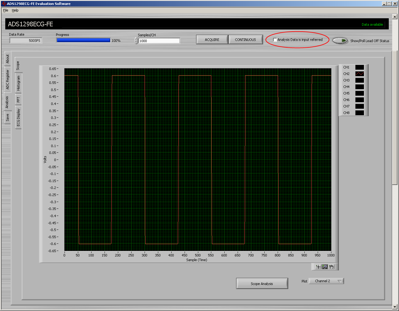
But the PGAs in the ADS1298R doesn't work. For example, I set PGA as 12, the captured figure is smaller than PGA6 one.

And even the outputs from the test signals are always same at any PGA.

Am I doing something wrong??

Here is one more problem that the output signal is not clear.

Can anyone tell me general setting of the resisters for non ecg signal??

Additionally, I do not need WCT, I will just use differential inputs from the load cell, and I want to amplify them.

  • **TI EDIT February 20th 2019; FOR GENERAL ADS129x ASSISTANCE, PLEASE SEE NEW BIOPOTENTIAL FAQ LOCATED HERE**

    Hi Sang-Uk Jeon,

    The chart here is input referred. So, for example, if the input were 100mVpp, then the chart would show 100mVpp.

    I'm not quite certain what you are asking for the next part, though.  Are you asking what the default register settings are? Or are you asking for specific registers?

    Regards,

    Michael

  • Thank you for your reply, Michael.

    First of all, I am sorry about my uncertain questions. My poor English....

    If so, as you said 100mVpp input would be shown 100mVpp, what are PGA settings for? 1,2,3,4,6,8,12???

    Here is more detail situation.


    I just changed type of input to Test Signal. Other settings are same as defaults.

    This is the result.

    Vpps are 2mV. Then I changed PGA 6 to 12.

    I thought results should be 4mV.

    But..

    same as before...

    Is it right way???


    And next question is chart is not clear.

    Input was just 2mVpp, 2Hz of square wave.

    As you can see, output is not clear at all.

    My purpose is to amplify inputs from load cells. I mean it is not for ECG signals. But I need 8 channels. 

    Can you give me some suggestions? I mean other chips.

  • Hi Sang,

    The display on the ADS1298R software is always input referred so using a 200mV signal should display a 200mVamplitude in the scope tab regardless of your gain setting - the signal is actually being amplified inside the PGA on the ADS1298R, it's just being displayed on your PC with the gain factor take out.  If you would like to see the data without the gain factor correction, download and install the ADS1298ECGFE-PDK software.  This is essentially the same as the ADS1298R code with the respiration features removed.  The code will still run with the ADS1298RECGFE-PDK hardware so there are no issues there.

    One other difference is that the ADS1298ECGFE-PDK software has a check box at the top of the display that allows you to turn off the gain fator correction so you see the data at the output of the ADC.  I've attached a couple screen shots for you in a zip archive to show the differences.  Now, speaking of your square wave input, how do you have your generator connected to the EVM?

    8561.2HzSquareWave.zip


  • Thanks a ton, Tom.

    I got the way how to amplify signals  by ADS1298 software.

    I have opened JP31 and connected inputs to right side of JP31.

    I think it is directly conneted to IN3P and IN3N on ADS1298R chip.

    Am I doing wrong?

    Please correct me.

  • Hi Sang-Uk,

    In the screen shot I sent you, I used an Agilent 33522A generator with a BNC to ball clip cable on the right side of JP32.  You are correct in that JP31 goes to CH3, there should be no difference though. 

    Are you running the ADS1298R with bipolar supplies?  If so, ground the IN(N) terminal to TP1 or TP11 and apply your signal (with no offset) to the IN(P) terminal and you should be able to get a clean signal displayed on the scope tab.  If you are running with 0-5V inputs, you'll need to offset your input signal and apply a DC voltage (Vref/2 for example) to the IN(N) side to stay within the common mode limits of the device.

  • Thank you for your help, Tom.

    You really saved me a lot.

    I think and hope that this question is gonna be the last question.

    When input signal and PGA are small, I can read specific values in scope tab like 2.02mVpp.

    But when they are large, I can't.

    For example, output is 2.3Vpp, I only can read 2.3E+00.

    I need more specific digits..... is it possible???

  • Hi Sang,

    I'm happy to hear that you are progressing!  The best way to see more data is to use the 'Save' tab.  Save your Scope Analysis in Volts to a file.  This can then be opened up in Excel and you can get the additional significant digits you need by Format -> Cells -> Scientific, decimal places...