This thread has been locked.

If you have a related question, please click the "Ask a related question" button in the top right corner. The newly created question will be automatically linked to this question.

ADS131M08: /DRDY pin stops toggling during continuous mode acquisition

Part Number: ADS131M08

Hello everyone,

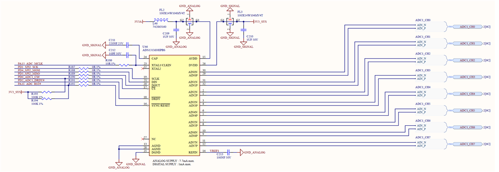
I've got the circuit below with the CLKIN of the ADS131 running at 8 MHz. The clock signal is generated by a timer in the microcontroller. The word-length is set as 24-bit and the Output Data Rate configured as:

  • OSR (over-sampling ration) = 256
  • ODR = 8 MHz/(2*256) = 15,625 kHz

I'm writing because I noticed that the /DRDY pin stops toggling in a stochastic way for 4.1 ms during the acquisition:

Here's also a zoom-in screenshot in the area where the last /DRDY before the 4.1 ms interruption is toggled and read:

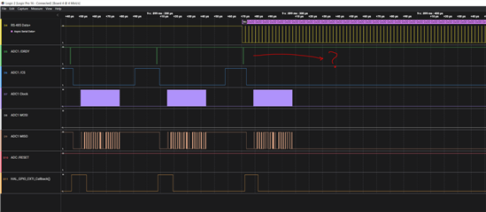
In this other question, Cole Macias mentioned that a possible cause of the /DRDY signal being shifted is the clock of the ADC. I verified the CLKIN of the ADS131 as well and it's not interrupted when the /DRDY does:

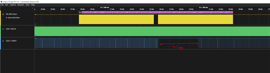
Here's a zoom-in version of the same capture, notice that the period of the clock signal is ~ 8 MHz:


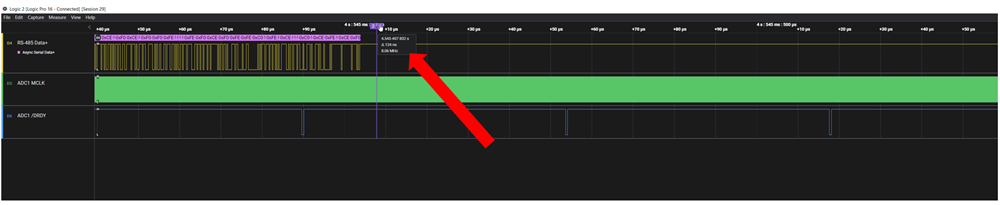
I was wondering if you guys have any idea of why the ADC might stop pulling down the DRDY pin? 

As an additional observation, I noticed that this issue only happens after a 10 Mbit/s transmission over a serial port starts (see yellow signal). This made me thing of an EMC-related issue. However, after reducing the baud-rate from 10 to 1 Mbit/s the problem is still there.

I'd really appreciate your comments on this issue.

Thanks in advance for the help!

Bests,

Juan  

  • Hi Juan,

    I noticed that you have two different ground connections (GND_Analog and GND_Signal) in your schematic, have you shorted them in your circuit? I could not see them in your schematic.

    Do you share the SPI bus with other devices except the ADC? are your data correct after the /DRDY is recovered?

    Is it possible to completely stop the data transmission (RS-485 Data+) for test purpose? it seems that there is a relationship between them based on your timing.

    Best regards,

    Dale

  • Hi Dale,

    Thanks for your answer. About the GND_Analog and GND_Signal grounds yes, they are shorted through an LC filter, so at DC freq. they are effectively connected together:

    The SPI is used exclusively with the ADC, there's no other peripheral sharing the bus and the data is correct after /DRDY is pull-up. 

    Regarding the RS-485 transmission, when this is not present the /DRDY interruption never occurs. It's only there after a few seconds of starting the transmission.

    /****************************** EDIT ******************************/

    I managed to solve my issue to avoid the /DRDY interruption, however I still can't explain why the ADC  was stopping the toggle of the DRDY pin. The issue was on the firmware. Basically the priority level for the SPI interrupt was the highest but also shared with another SPI and two timers. Even though from the datasheet of the microcontroller is explained that two interrupt with the same priority can not interrupt each other, it looks like that was not the case. I solved the issue by leaving the SPI alone in its priority level and moving all the rest peripherals to a lower level. Now the /DRDY interruption does not occur. However, I would assumed that this should be decoupled from what the microcontroller does... right? Is it maybe related to the fact that the /CS remains pulled-down after the ADC's FIFO is readout?

    Bests,
    J. 

  • Hi Juan,

    Thank you for your update. I'm glad you have found the software issue on your microcontroller.

    The "FIFO" on the ADS131M08 is actually is not a real FIFO, there is a possible reason your software issue caused the phenomenon, the ADC stopped toggling and only output short high-low pulses on /DRDY when there is no readout of conversion data, maybe your scope did not capture the short high-low pulses on the /DRDY.

    Regards,

    Dale